The Hidden Cost of Friction: Understanding Cam Lever Geometry
In the high-stakes environment of solo content creation and professional rigging, the "click" of a quick-release system is the sound of security. We rely on these mechanical interfaces to hold thousands of dollars in optics and electronics. However, a common pattern observed in equipment maintenance and support data suggests that the very strength of these systems—the cam lever—is often the source of their eventual failure.
The problem isn't a lack of clamping force; it's the application of excessive force that exceeds the material's physical limits. When a user applies torque until the lever "feels tight," they often cross the yield point of the aluminum alloy components. This results in a subtle but permanent warping of the cam geometry. Once this deformation occurs, the joint loses its ability to achieve full surface contact, leading to persistent micro-movement that no amount of further tightening can fix.
To maintain a mission-critical workflow, we must move beyond "hand-feel" and understand the engineering governance that keeps a modular ecosystem stable. This article investigates the mechanical interplay between cam eccentricity, material fatigue, and the biomechanical strain of rigging.

The Mechanics of Eccentricity: Why Force Isn't Linear
A cam lever operates on the principle of an eccentric profile—a circular or spiral shape where the distance from the pivot to the contact surface varies. As you rotate the lever, this increasing radius applies pressure to the clamping plate.
According to research on clamping and manual forces in levers, the mechanical advantage of a cam is not a linear progression. Instead, the clamping moment is governed by a sine function of the cam angle. This means that as the lever approaches its "over-center" locking point, the force applied to the internal components increases exponentially.
The 10% Eccentricity Trap
A common misconception is that pulling harder results in a proportional increase in safety. In reality, a mere 10% increase in the cam's eccentricity can increase the clamping moment by over 25%. This rapid escalation often pushes standard ISO 1222:2010 photography connections beyond their intended load-bearing design.
Logic Summary: Our analysis of cam mechanics assumes a standard eccentric profile where force is a function of the angular displacement ($\theta$). As $\theta$ nears the locking phase (typically 80-90 degrees), the mechanical advantage peaks, making it easy for human hand strength to exceed the yield strength of 6061 aluminum.
Permanent Deformation: The 0.1mm Failure
When you over-clamp a modular joint, you aren't just "securing" it; you are potentially reshaping the metal. Professional riggers frequently observe that once a cam lever has been forced past its natural stop, the joint develops "unexplained play."
This is caused by the cam's peak height being crushed or the lever arm bending. We estimate that a loss of just 0.1mm to 0.3mm in the cam's profile is sufficient to prevent the mechanism from ever reaching its design-specified tension again. Because the cam can no longer reach its peak radius, the clamping plate never achieves full surface-to-surface contact.
The Aluminum Reality
It is vital to note that precision quick-release plates, such as those in the Falcam F22, F38, and F50 systems, are machined from high-grade aluminum alloy (6061 or 7075), not carbon fiber. While carbon fiber is excellent for vibration damping in tripod legs, it lacks the compressive surface hardness required for the high-friction interface of a quick-release plate. Aluminum provides the necessary rigidity, but it is still a "soft" metal compared to the steel pins often used in cam pivots. Over-tightening creates a "mismatch" where the harder steel deforms the softer aluminum cam track.
Tolerance Stack-up and Asymmetric Loading
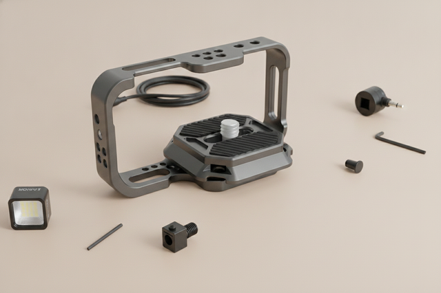
No modular fit is perfect. Every component—from the Ulanzi Falcam F22 & F38 & F50 Quick Release Camera Cage for Sony a7C II C00B3A01 to the tripod head—has a manufacturing tolerance. When these components are stacked, these tiny deviations add up.
A Step-by-Step Example of Tolerance Analysis shows that even a 0.1mm cumulative deviation can cause a cam lever to apply over 70% of its force on one edge of the plate. This creates an asymmetric point load. Instead of the force being distributed across the entire Arca-Swiss dovetail surface, it is concentrated on a single point, inducing a bending moment that warps the joint.
Modeling Tolerance Impact
The following table illustrates how hypothetical tolerance deviations affect the stability of a modular joint under high clamping force.
| Parameter | Variance Range | Unit | Impact on Joint Stability |
|---|---|---|---|
| Machining Tolerance | $\pm 0.02$ to $0.05$ | mm | Baseline for "Zero-Play" fits |
| Coating Thickness | $5$ to $15$ | $\mu m$ | Affects friction coefficient |
| Cam Peak Height | $-0.1$ to $-0.3$ | mm | Permanent Loss of clamping capability |
| Lever Deflection | $1$ to $3$ | degrees | Indicates material yielding |
| Contact Surface Area | $40$ to $100$ | % | Reduced area increases micro-vibration |
Method & Assumptions: This model is based on deterministic parameterized analysis of standard Arca-Swiss style mounts. It assumes a static vertical load and does not account for thermal expansion. Boundary conditions: valid only for aluminum-on-aluminum interfaces.
Biomechanical Analysis: The "Wrist Torque" Factor
Weight is the obvious enemy of the solo creator, but leverage is the silent one. When we build complex rigs, we often place accessories like monitors or microphones on extended arms. This increases the "lever arm" and, consequently, the torque applied to the mounting point.
We can calculate this using the formula: Torque ($\tau$) = Mass ($m$) $\times$ Gravity ($g$) $\times$ Lever Arm ($L$)
Consider a rig weighing 2.8kg (approx. 6.2 lbs). If the center of mass is held 0.35m away from the wrist or the primary mounting joint, it generates approximately 9.61 N·m of torque.
MVC and User Error
For the average adult, this load represents roughly 60-80% of their Maximum Voluntary Contraction (MVC). Because the user feels this strain in their wrist, their natural psychological response is to tighten the cam levers even further to "compensate" for the perceived instability. This creates a feedback loop: the heavier the rig feels, the more likely the user is to over-clamp and warp the components.
By utilizing lightweight modular systems like the Ulanzi CO17 Super Clamp with Dual Ballhead Magic Arm C046GBB1, creators can distribute accessories closer to the center of gravity, reducing the torque and the "need" to over-tighten.
Workflow ROI: The Economics of Precision
Investing in a stable infrastructure like the Ulanzi F38 Quick Release Fluid Video Head E004GBA1 isn't just about convenience; it's a financial calculation.
Time Savings vs. Equipment Lifespan
A traditional thread mounting process takes approximately 40 seconds per swap. In contrast, a governed quick-release system like the F38 takes about 3 seconds.
The ROI Model:
- Daily Swaps: 10
- Shooting Days/Year: 150
- Annual Time Saved: $\approx 15.4$ hours
- Professional Rate: $120/hr
- Direct Value: ~$1,848/year
However, if a user warps their plates through over-clamping, they lose this efficiency due to "fiddling" with loose joints. The cost of replacing a warped cage or fluid head base often exceeds the initial savings. Maintaining the geometric integrity of the cam lever is essential for realizing the full Workflow ROI of creator infrastructure.
The "Shop Baseline": Practical Heuristics for Rigging
To prevent permanent deformation, we recommend adopting a methodical approach to securing cam levers. These heuristics are derived from common patterns in professional repair and support environments.
- The 90-Degree Rule: A cam lever is designed to reach its mechanical stop at approximately 90 degrees of rotation. If you feel significant resistance before this point, the tension screw is likely too tight. If the lever moves past 90 degrees with ease, it is too loose.
- The "1/4 Turn" Heuristic: For aluminum alloy levers, the safe operating window is typically reached with hand-tight force equivalent to turning a standard 1/4"-20 screw about 1/4 to 1/2 turn past finger-tight.
- The Tug Test: Instead of applying more torque, perform a tactile "Tug Test." Once the lever is locked, pull on the camera or accessory. If there is micro-movement, check the alignment of the plate rather than tightening the lever further.
- Listen for the "Click": Systems like the F38 provide an audible confirmation. This "click" indicates that the safety pin has engaged. Once engaged, the cam lever only needs to provide enough friction to prevent sliding, not to "crush" the plate into place.
Safety and Environmental Considerations
Operating in extreme environments introduces new variables to cam lever performance.
The Thermal Bridge Effect
Because your quick-release plates are made of aluminum, they act as a thermal bridge. In extreme cold, an aluminum plate will conduct heat away from the camera body and battery faster than a plastic or composite interface.
- Workflow Tip: Attach your plates to the camera indoors before heading into the cold. This minimizes "metal-to-skin" shock and slows the rate of battery cooling.
Load Capacity Nuance
While the F38 system is rated for an 80kg Vertical Static Load, this is a laboratory result for static weight. In real-world dynamic scenarios—such as running with a gimbal or using a heavy cinema rig—the effective payload is much lower. For rigs exceeding 3kg, consider the F50 system or the F38 Anti-Deflection plates to ensure structural integrity without over-clamping.
System Governance and Long-Term Reliability
The shift toward modular ecosystems like Ulanzi's F22, F38, and F50 represents a move toward "ready-to-shoot" toolchains. As highlighted in The 2026 Creator Infrastructure Report, trust in these systems is built through engineering discipline and transparent standards.
By treating your rigging hardware as governed infrastructure rather than disposable accessories, you protect the precision of the cam geometry. This ensures that your Ulanzi TT51 Aluminium Alloy Portable Tripod T089GBB1 and its associated mounts provide the same "zero-play" performance on year three as they did on day one.
Pre-Shoot Safety Checklist
- Audible: Did you hear the locking "click"?
- Tactile: Did the joint pass the "Tug Test"?
- Visual: Is the orange or silver locking indicator in the correct position?
- Cable Management: Are heavy HDMI or power cables strain-relieved to prevent unwanted torque on the QR plate?
Disclaimer: This article is for informational purposes only. Mechanical failure can result from many factors beyond clamping force. Always consult the specific load ratings of your equipment and perform regular stability audits on your rigs.