The Alpine Optical Frontier: Engineering for the Cryosphere
Quick Action Box: If You Only Have 60 Seconds
- Pre‑mount aluminum plates indoors. Attach quick‑release plates and aluminum mounts while you’re still warm inside, so the light, battery, and plate share a stable starting temperature before you step into the cold.
- Give your kit ~30 minutes to acclimatize. Before cranking LEDs to full power, let lights and mounts sit in the outside air so they cool gradually and are less likely to fog or crack.
- Keep spare batteries warm on your body. Store them in an inner pocket and rotate them regularly; expect shorter runtimes in the cold and plan extra capacity.
In the high-altitude theaters of the Himalayas or the Arctic, photography and cinematography transition from a creative pursuit to an exercise in extreme systems engineering. For the adventure creator, equipment is not merely a set of accessories; it is mission-critical infrastructure. While much industry discourse focuses on camera sensor performance, the true "tail-risk" in extreme environments often resides in the peripheral ecosystem—specifically, the thermal stability and mechanical integrity of portable lighting and mounting interfaces.
The prevailing industry heuristic suggests that battery depletion is the primary failure mode in the cold. However, field experience and material science data point to a more complex reality. From the ductile-to-brittle transition of polymers to the convection cooling paradox at 4000 meters, understanding the "Wilderness Optics" of portable LEDs is essential for mitigating risk and improving the odds of professional-grade output in sub-zero conditions.
The Material Science of Impact: The Polycarbonate Breaking Point
A common misconception among creators is that the plastic housings of pocket lights are "ruggedized" enough for alpine use. In reality, most consumer and prosumer electronics utilize polycarbonate or ABS blends for lenses and diffusers. These materials undergo a ductile-to-brittle transition (DBT) as temperatures drop.
According to reference data on Ductile / Brittle Transition Temperatures, polycarbonate can begin this transition near 0°C (32°F). By the time a creator reaches around -20°C (-4°F), published curves and example datasets show that the material’s impact toughness can drop dramatically—often by something on the order of 90% compared to room temperature (literature-based example value for -20°C impact tests; exact values depend on resin, loading rate, and sample geometry). In this state, a minor drop or a sharp knock against a climbing harness that would be inconsequential at room temperature can be much more likely to cause the lens or housing to crack.
This brittleness is compounded by the glass transition of internal polymers. The potting compounds, switch diaphragms, and even wire insulation can see a very large stiffness increase near their glass transition temperature ($T_g$). Some dynamic mechanical analysis data suggest order-of-magnitude changes in modulus (e.g., up to about 10,000x in certain formulations) as polymers move from rubbery to glassy states (order-of-magnitude illustration based on dynamic modulus measurements; not a single universal constant). This leads to a cascade of potential mechanical issues:
- Switch Behavior Changes: Capacitive touch sensors often perform poorly in high-humidity or freezing conditions. Many practitioners prefer fully mechanical switches for their tactile reliability with gloved hands.
- Solder Joint Stress: Differential thermal contraction between the aluminum heat sink and the PCB can contribute to solder joint fatigue during rapid temperature shifts, especially if the product is repeatedly cycled between warm and very cold conditions.
Modeling Note: Material Performance at -20°C
The table below summarizes illustrative parameter values used to reason about material behavior in alpine scenarios. These are based on typical ranges reported in references such as ASTM E1876 dynamic modulus testing and polymer DBT literature, not on a single proprietary test of a specific product. Treat them as engineering heuristics / example values, not guaranteed specs for any given light:
Parameter Value Unit Rationale / Source Type Polycarbonate Impact Toughness Loss ~90% % Literature-based example around -20°C (polymer DBT curves; actual value depends on resin & test method) Polymer Stiffness Increase ~10,000x Factor Order-of-magnitude illustration approaching Tg (dynamic modulus data; varies by formulation and frequency) Acclimatization Window ~30 Minutes Field heuristic to reduce thermal shock and fogging, not a strict safety limit Aluminum 6061 Thermal Conductivity ~167 W/m·K Typical handbook value for 6061-T6 (materials datasheet) Fatigue Limit (Aluminum) ~95 MPa Representative fatigue limit range for 6000-series aluminum under cyclic loading (materials references)
The Optical Barrier: Dew Point and Thermal Shock
While battery failure is a nuisance, lens fogging is often a definitive shot-killer. Fogging occurs when the temperature of the optical surface drops below the dew point of the surrounding air. Practitioners often observe that fogging is one of the first optical issues to show up, sometimes at temperature differentials as small as roughly 10–15°C (18–27°F) (field-observation range; not a hard threshold).
Moving a pocket light from a warm internal jacket pocket (~32°C) to a cold alpine night (~8°C) creates an immediate condensation risk. This is not merely an external issue; internal condensation can form on the LED emitter itself, potentially compromising beam clarity and causing light scatter.
To mitigate this, the "30‑Minute Acclimatization Heuristic" is a strong recommendation rather than a law of physics. In practice, giving your gear on the order of 30 minutes to transition gradually between environments tends to reduce rapid temperature shocks and fogging (field-based rule of thumb derived from cold-weather shooting workflows).
Furthermore, the use of aluminum mounting interfaces, such as precision-machined 6061 aluminum quick-release plates, introduces a "thermal bridge" effect. While aluminum provides excellent rigidity, it also conducts cold rapidly to the camera or light body. Attaching these plates indoors before deployment helps manage the rate of battery cooling by establishing a shared thermal mass before exposure.
The Altitude Paradox: Overheating in the Cold
High-altitude environments (around 4000m and above) introduce a physical paradox: small electronics can overheat even when the ambient air is freezing. This is driven by reduced air density. At 4000 meters, typical standard-atmosphere tables put air density at roughly 0.82 kg/m³, compared to about 1.225 kg/m³ at sea level—a reduction on the order of 30% (standard-atmosphere approximation; varies with weather).
Since portable LEDs rely heavily on convection cooling to dissipate heat from the driver and emitter, the thinner air is significantly less efficient at carrying heat away.
- Convection Efficiency Drop: A light running at 100% output that is thermally stable at sea level may be more likely to trigger a thermal protection step-down or shutdown at altitude, because the same wattage produces higher internal temperatures in thinner air (engineering expectation based on convection principles, not a guarantee for every model).
- Internal Degradation Risk: Sustained high internal temperatures in a freezing external environment can accelerate the degradation of LED phosphor and internal capacitors over time, leading to color shift (for example, measurable via TLCI-2012) and reduced lifespan.
Creators must balance output with these atmospheric constraints. A simple thermal and battery model for a typical 2000mAh pocket light at 80% brightness suggests that runtime can drop significantly in deep cold—often in the ballpark of a 30–40% reduction at -20°C compared with room-temperature conditions (combined effect of lithium-ion performance loss plus driver behavior; modeled estimate, not a lab spec). The thermal risk of running at maximum power in thin, cold air remains a critical secondary failure point.
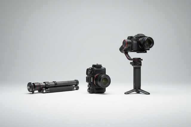
Biomechanical Efficiency: The Leverage of Lightweight Rigging
In the wilderness, "lightweight" is a survival strategy, not just a preference. However, mass reduction must not come at the cost of structural rigidity. The higher end of adventure imaging is shifting toward modular, ecosystem-based rigging to manage wrist torque.
Weight alone does not dictate fatigue; the lever arm does. When accessories like monitors or lights are mounted far from the camera’s center of gravity, they create significant torque on the creator's wrist and the mounting interface.
The "Wrist Torque" Analysis
Using the formula: Torque ($\tau$) = Mass ($m$) $\times$ Gravity ($g$) $\times$ Lever Arm ($L$)
Consider a 2.8kg cinema rig held 0.35m away from the wrist. This setup generates approximately 9.6 N·m of torque (back-of-envelope calculation using $g \approx 9.8$ m/s²; example only). For many adults, that kind of continuous load represents a substantial fraction of their Maximum Voluntary Contraction (MVC), which helps explain the rapid onset of fatigue. By utilizing ultra-low-mass modular mounts (such as F22 or F38‑style quick releases), creators can bring accessories closer to the center of gravity, reducing the lever arm and extending their effective shooting time.
Workflow ROI: The Value of Seconds
In extreme cold, every second spent fiddling with frozen screw threads is a risk to both the shot and the creator's comfort or even safety (for example, increased frostbite exposure time).
| Metric | Traditional Thread | Quick Release (F38/F22) |
|---|---|---|
| Swap Time (Avg) | ~40 Seconds | ~3 Seconds |
| Annual Time Saved* | ~49 Hours | — |
| Estimated Value** | ~$5,900 | — |
*Based on 60 swaps/shoot, 80 shoots/year; simple time-per-swap multiplication (illustrative productivity model).
**At a notional professional rate of $120/hr; adjust to your own rate and shoot volume.
As noted in The 2026 Creator Infrastructure Report, an industry report from a vendor rather than a neutral standard body, the shift toward "ready-to-shoot" toolchains is a response to the need for more reliable, predictable workflows. Trust in gear is built through engineering discipline and stable interfaces that perform as expected under stressful conditions, not through absolute performance guarantees.
Mission-Critical Field Checklist
To improve system-level reliability in alpine conditions, creators can adopt the following cold-weather workflow (inspired by "zero-fail" thinking, but not a guarantee against all failures):
- Thermal Prep: Attach all aluminum mounting plates to devices indoors to minimize thermal shock. Let the assembly equalize before going outside.
- Acclimatization: Allow gear roughly 30 minutes to reach ambient temperature before powering on high-output LEDs at full blast (field heuristic to reduce fogging and material stress; shorten or extend based on conditions).
- The "Tug Test": After engaging any quick-release mechanism, perform a physical pull-test. Listen for the audible "click" (if present on your system) and visually verify the locking pin or latch status.
- Power Management: Keep spare batteries in an internal pocket close to body heat. In many lithium-ion systems, you can see on the order of a 40–50% drop in runtime at around -10°C compared to room-temperature lab specs (based on vendor cold-weather guidance and field reports, not a universal guarantee for all packs).
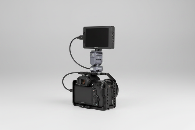
- Cable Strain Relief: Use modular cable clamps or guides to prevent heavy HDMI or power cables from creating unwanted torque on mounting points, which can loosen connections in high-vibration (windy) scenarios.
How We Think About the Numbers (Modeling Approach)
Where this guide references percentages or runtime changes, they are based on a mix of:
- Published reference data (e.g., polymer DBT curves, standard-atmosphere tables, LED and battery datasheets).
-
Engineering heuristics and simplified models, such as:
- 1D thermal resistance models for heat flow from LED die → board → aluminum plate → air.
- Basic convection relationships (cooling effectiveness decreasing with lower air density and airflow).
- Simple energy calculations (battery capacity in Wh divided by approximate load power to estimate runtime, then adjusted using manufacturer cold‑temperature derating curves where available).
- Field observations from cold-weather shoots, used to sanity-check whether the modeled directions and magnitudes match real-world behavior.
These methods are intended to help you reason about trends and orders of magnitude, not to provide certification-grade limits for your specific gear. Always refer to your light and battery manufacturer’s datasheets and, where available, independent test data for precise specifications.
Engineering the Future of Adventure Imaging
The future of wilderness imaging lies in the move away from "fast-fashion" accessories toward engineered solutions. Brands that prioritize standards such as ISO 1222:2010 tripod connections and IEC 62133-2 battery safety are helping set expectations for the next generation of explorers.
By understanding the interplay between material science, atmospheric physics, and biomechanical leverage, adventure creators can spend less energy fighting their gear and more on storytelling. In the cryosphere, stability is not just about a steady shot—it is about the integrity of the entire ecosystem.
Disclaimer: This article is for informational purposes only. Filming in extreme cold and high-altitude environments involves significant physical risk. Always consult with professional mountain guides and ensure all equipment is rated for the specific conditions of your expedition. Your actual runtimes, failure modes, and safety margins will vary with gear choice, maintenance, and environmental conditions.
Sources
- ISO 1222:2010 - Photography — Tripod Connections
- IEC 62133-2:2017 - Safety Requirements for Lithium Cells
- EBU R 137 / TLCI-2012 - Television Lighting Consistency Index
- The 2026 Creator Infrastructure Report — industry report / vendor blog
- SpecialChem: Ductile / Brittle Transition Temperature — polymer DBT overview