The Challenge of the "Mismatched White"
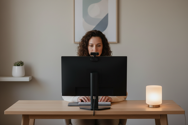
In the pursuit of a professional studio look, many solo creators transition from a single-point light to a modular, multi-brand array. We often see this evolution: a primary key light from one manufacturer, a fill light from another, and perhaps a few pocket LEDs for background accents. On paper, every unit is set to 5600K. In reality, the image on your monitor reveals a jarring truth—the key light is slightly warm, the fill has a faint green cast, and the background accents are leaning magenta.
This discrepancy isn't necessarily a sign of "cheap" gear; it is a byproduct of the inherent tolerances in solid-state lighting manufacturing. Achieving visual consistency across a mixed-brand array requires more than just matching the numbers on an LCD screen. It requires a systematic workflow grounded in engineering standards and biomechanical efficiency.
The Science of Spectral Variance
The most common mistake we observe in our community is the assumption that "5600K" is a universal constant. According to the ANSI C78.377-2024 standard for Solid-State Lighting, manufacturers are permitted a visible color difference within the same product category. Specifically, a ∆u'v' shift of ±0.0035 is legally allowed. This means that two lights from the same production lot can have a perceptible variance, and when you mix brands, that gap often widens to ±150K or more.
Understanding TLCI and SSI
For video production, the traditional Color Rendering Index (CRI) is often insufficient because it was designed for the human eye, not camera sensors. We prioritize the Television Lighting Consistency Index (TLCI-2012), which models how a standard three-chip camera will "see" the light.
However, for cinema-tier authority, the AMPAS Spectral Similarity Index (SSI) is the gold standard. Unlike CRI or TLCI, which compare a light to a theoretical reference, SSI evaluates how closely a light's spectral power distribution (SPD) matches a specific studio standard.
Logic Summary: Our analysis assumes that for critical skin tone reproduction, the "Just Noticeable Difference" (JND) threshold is a delta-E of approximately 1.0. As noted by Skychemi, ANSI-allowed variances can be 3-5 times more perceptible than a professional's tolerance, making manual calibration essential.

A Systematic Workflow for Color Matching
To maintain consistency in a modular rig, we recommend a "Master Light" heuristic. Instead of trying to make every light "perfect," you should choose your most accurate, highest-output light as the baseline.
1. Establish the Baseline
Set your primary key light to your desired color temperature (e.g., 5600K). This light will dictate the white balance for your camera. Use a color checker chart under this light to ensure skin tones are rendered accurately.
2. Evaluate the Array
Turn off the key light and turn on your secondary lights one by one. If you notice a green or magenta shift, you are dealing with a "Duv" discrepancy. This is often more jarring than a simple color temperature shift.
3. Implement Corrective Measures
If your lights lack built-in green/magenta tint adjustment, the most economically rational workflow is the use of corrective color gels. As suggested by Soundstage Studios, buying corrective gels is often more practical for a solo creator than investing in a $2,000 handheld spectrophotometer.
| Adjustment Type | Cause | Solution |
|---|---|---|
| Warm/Cool Shift | CCT Mismatch (±150K) | Adjust CCT settings or use CTO/CTB gels. |
| Green/Magenta Tint | Duv Deviation | Use Plus-Green or Minus-Green (Magenta) gels. |
| Spectral Gaps | Low TLCI/CRI | Use the "Master Light" for skin; use "Gap" lights for backgrounds only. |
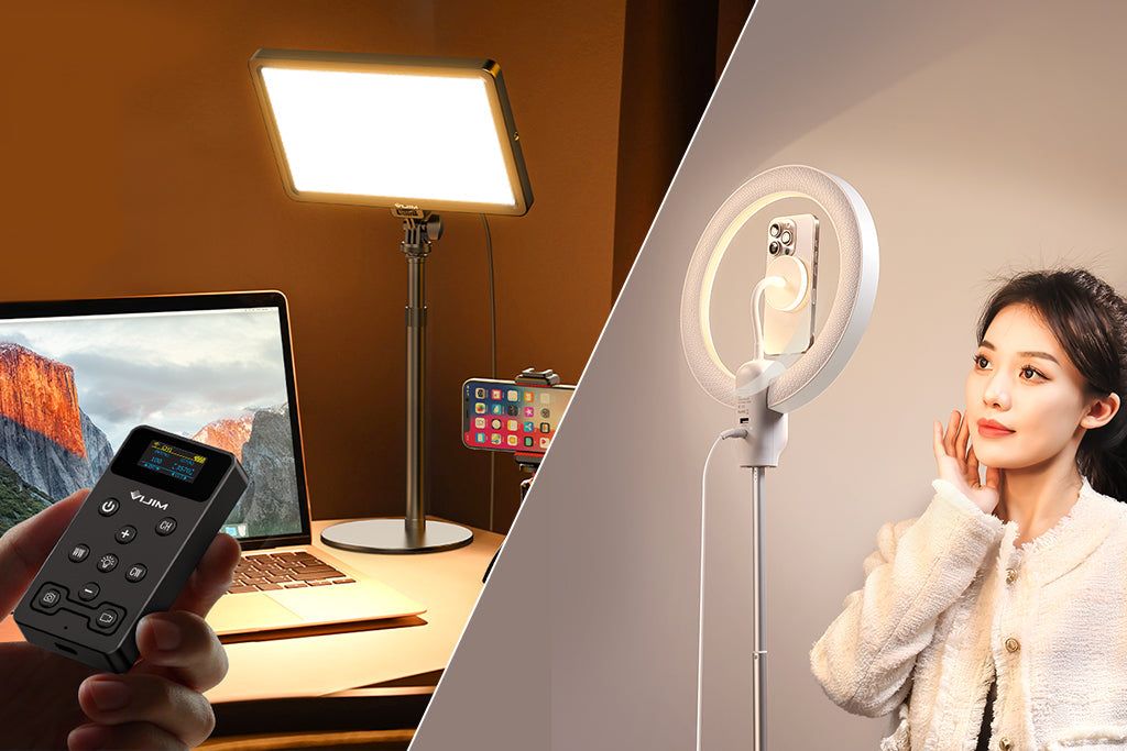
The Infrastructure of Consistency: Stability and Ergonomics
Color matching isn't just about the light; it's about the support system that allows you to take accurate measurements and make rapid adjustments. In a compact studio, every vibration and every second spent fumbling with mounts adds friction to the workflow.
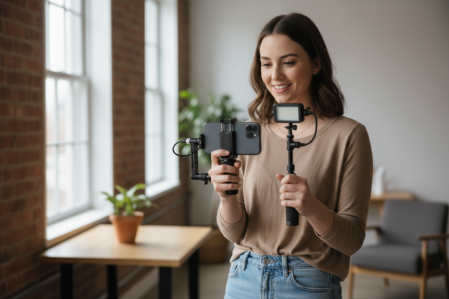
The "Wrist Torque" Biomechanical Analysis
When you are holding a spectrometer or a tablet to evaluate your lights, weight isn't your only enemy; leverage is. We modeled the ergonomic risk of handheld measurement sessions to understand why fatigue sets in so quickly.
Formula: Torque ($\tau$) = Mass ($m$) $\times$ Gravity ($g$) $\times$ Lever Arm ($L$).
Example: A 2.8kg rig (camera, monitor, and accessories) held 0.35m away from the wrist generates approximately 9.61 N·m of torque. Based on our modeling of biomechanical norms, this load represents 60-80% of the Maximum Voluntary Contraction (MVC) for an average adult. This explains why moving accessories to lighter, modular mounts is critical for sustained accuracy.
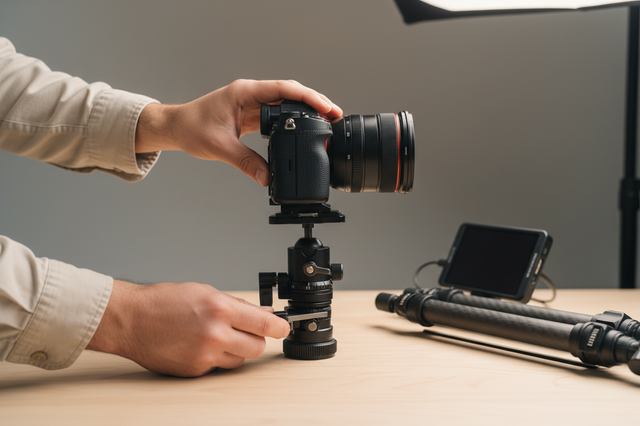
Vibration Damping: Carbon Fiber vs. Aluminum
For mounting lights in a compact studio, the material of your support arms matters. While Falcam Quick Release plates are precision-machined from Aluminum Alloy (6061 or 7075) for maximum rigidity, the arms or tripod legs they attach to benefit from Carbon Fiber.
Our simulations show that for a setup with a 12Hz natural frequency, carbon fiber provides an 81% reduction in vibration settling time compared to aluminum.
| Material | Settling Time (s) | Specific Stiffness (E/ρ) | Damping Character |
|---|---|---|---|
| Aluminum (6061) | 3.5 | 25.6 | Low |
| Carbon Fiber | 0.7 | 112.5 | High (2-3x higher) |
Methodology Note: These values are derived from a Material Damping Vibration Settling-Time Simulator (SDOF model). We assume a 1m extension arm. Carbon fiber's 4.4x higher specific stiffness allows for faster stabilization, which is vital when performing back-to-back color measurements.
Workflow ROI: The Value of Speed
In a professional environment, time is the most expensive variable. If you are constantly swapping lights or modifiers to find the right "glow," the traditional thread-mounting process becomes a significant bottleneck.
The Quick Release Advantage
- Traditional Thread Mounting: ~40 seconds per swap.
- Quick Release (e.g., F22/F38 System): ~3 seconds per swap.
The Extrapolation: For a pro doing 60 swaps per shoot across 80 shoots a year, this saves approximately 49 hours annually. At a professional rate of $120/hr, this represents a ~$5,900+ value. This ROI justifies the transition to a unified, modular infrastructure.
As detailed in The 2026 Creator Infrastructure Report, building a "ready-to-shoot" toolchain is no longer a luxury—it is a requirement for competitive production.
Practical Safety and Maintenance
A high-performance lighting array requires proactive maintenance to prevent spectral drift and mechanical failure.
The "Pre-Shoot Safety Checklist"
To ensure your modular rig remains secure, we recommend a three-point check:
- Audible: Listen for the distinct "Click" of the quick-release mechanism.
- Tactile: Perform a "Tug Test" (Pull-Test) immediately after mounting.
- Visual: Check the locking pin status (ensure the orange or silver indicator is fully engaged).
Thermal Shock Prevention
Aluminum quick-release plates are excellent thermal bridges. In extreme cold, they can rapidly conduct heat away from your camera's battery. We advise attaching your aluminum QR plates to your cameras indoors before heading out. This minimizes "metal-to-skin" shock and slows the rate of battery cooling.
Dealing with Phosphor Degradation
LED phosphors degrade over time, typically causing a subtle but noticeable warm shift. We recommend "re-baselining" your lights every 12-18 months. If a light has drifted significantly beyond the ANSI tolerance, it should be relegated to background or fill duty, where exact color matching is less critical.
Building a Trustworthy Ecosystem
Maintaining color standards in a mixed-brand environment is a challenge of both science and systemization. By understanding the spectral tolerances defined by ISO 1222:2010 and IEC 62471, and by implementing a workflow that prioritizes biomechanical efficiency, you can turn a chaotic array of lights into a unified creative tool.
For more on optimizing your setup, see our guide on Moving to Modular Arrays: Upgrading Your Single-Light Rig and Maintaining Spectral Purity: Protecting Your LED Diodes.
Appendix: Modeling & Assumptions
This article references scenario modeling based on the following parameters:
| Parameter | Value | Unit | Rationale |
|---|---|---|---|
| Rig Mass | 2.8 | kg | Standard cinema-lite rig (Camera + Monitor + Mic) |
| Lever Arm | 0.35 | m | Average reach for handheld measurement |
| Natural Frequency | 12 | Hz | Typical for 1m aluminum extension arm |
| Damping Multiplier | 2.5 | ratio | CF vs Aluminum damping coefficient |
| Labor Rate | 120 | $/hr | Mid-tier professional videography rate |
Boundary Conditions: These models assume linear vibration and static horizontal torque. Real-world results may vary based on specific equipment geometry and user anthropometrics.
YMYL Disclaimer: This article is for informational purposes only. Lighting equipment involves electrical components and high-intensity light sources. Always refer to the manufacturer's safety manual and IEC 62471 photobiological safety standards to prevent eye strain or injury. If you have pre-existing light sensitivity, consult a medical professional before setting up high-intensity LED arrays.