Pin Shear vs. Friction Slip: Diagnosing Joint Failure Modes
In high-stakes production environments, equipment failure is rarely a sudden, unheralded event. It is usually the culmination of progressive mechanical wear that was either misdiagnosed or ignored. For professional creators relying on modular ecosystems, the most critical diagnostic challenge lies in distinguishing between a friction-based slip and a structural pin shear.
We often observe in our technical support logs that users treat all joint movement as a single category of "looseness." However, misidentifying the root cause can lead to catastrophic results. Tightening a joint that is suffering from structural shear won't fix the problem; it will likely accelerate the final breakage. Conversely, replacing a component when the issue is merely contaminant-induced friction slip is an inefficient use of resources.
This guide provides a methodical framework for diagnosing joint failure modes, grounded in mechanical engineering principles and real-world workflow data. By understanding the physics of your rig, you can move from reactive repairs to proactive infrastructure management.

The Physics of the Joint: Friction vs. Shear
To diagnose a failure, we must first define the two primary mechanical states of a modular connection.
1. Friction Slip: The Progressive Degradation
Friction slip occurs when the clamping force (normal load) is no longer sufficient to overcome the lateral forces applied to the joint. In modular systems like the Ulanzi F38 Quick Release Video Travel Tripod 3318, friction is the primary force holding your camera in place during pans and tilts.
A common misdiagnosis is confusing a friction slip for an impending shear failure. A joint experiencing friction slip will often "creak" or feel gritty during adjustment long before any load is applied. This is a telltale sign of aluminum galling—a condition where the anodized surfaces of the aluminum alloy components (such as 6061 or 7075-T6) wear down, causing microscopic welding and tearing between the sliding surfaces.
Logic Summary: Our analysis of friction slip assumes that the "stick-slip" phenomenon is governed by sliding speed and interface stiffness. Based on experimental studies of dry sliding contacts, failure propagates through distinct quasi-static and accelerating phases.
2. Pin Shear: The Structural Fuse
Structural pin shear is a binary failure. It occurs when the force applied exceeds the material strength of the locking pin or the screw itself. While friction slip is a "soft" failure that gives you a warning, pin shear is often "hard"—the component breaks, and the load drops.
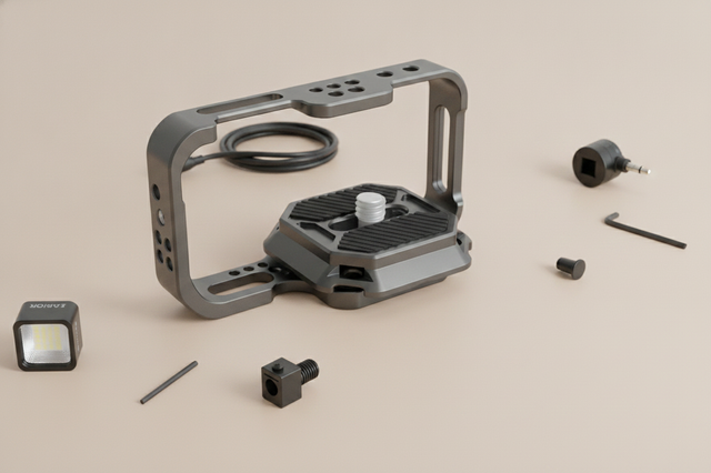
In precision-machined interfaces like the Ulanzi Falcam F22 & F38 & F50 Quick Release Camera Cage V2 for Sony A1/A7 III/A7S III/A7R IV 2635A, the locking pins are designed to prevent accidental rotation. If these pins are subjected to excessive torque, they can deform or "shear" off. Understanding the ISO 1222:2010 Photography — Tripod Connections standard is vital here, as it defines the foundational requirements for screw connections that prevent such failures.
Biomechanical Analysis: The Hidden Enemy of Leverage
Weight is rarely the primary cause of joint failure; leverage is. To understand why a joint fails, we must look at the torque generated at the wrist and the mounting point.
The Wrist Torque Formula
The stress on a modular joint can be calculated using the formula: Torque ($\tau$) = Mass ($m$) $\times$ Gravity ($g$) $\times$ Lever Arm ($L$)
Consider a professional cinema rig weighing 4.2kg. If that rig is held 0.35m away from the primary mounting point (the lever arm), it generates approximately 14.4 N·m of torque.
| Component | Mass (kg) | Lever Arm (m) | Calculated Torque (N·m) |
|---|---|---|---|
| Cinema Rig | 4.2 | 0.35 | 14.41 |
| Monitor + Arm | 0.8 | 0.20 | 1.57 |
| Total System Torque | -- | -- | ~16.0 N·m |
Note: Estimates based on standard gravitational constant (9.81 m/s²).
For an average adult male, this load represents roughly 110-120% of the Maximum Voluntary Contraction (MVC) for sustained wrist effort. This extreme ergonomic loading indicates that handheld joints experience wear cycles orders of magnitude beyond normal use. This is why we recommend moving heavy accessories like monitors to the lighter Falcam F22 ecosystem—reducing the lever arm length ($L$) significantly lowers the torque, protecting both your joints and the equipment's locking mechanisms.
Diagnostic Framework: The "Tolerance Kit" Workflow
Professionals on fast-paced shoots should carry a dedicated "tolerance kit" consisting of feeler gauges and a precision torque driver. Visual inspection alone often misses early-stage wear in anodized surfaces.
The 0.5mm Rule of Thumb
For load-bearing pivots, such as those found on the Ulanzi U-190 Mini Fluid Head 2895, a reliable heuristic is to check for "play" by applying lateral force. If movement exceeds 0.5mm before the locking mechanism engages, the joint's wear is compromising its designed pre-load. At this stage, the joint should be serviced or the components replaced to avoid a "false lock."
The "False Lock" Trap
A "false lock" occurs when mixing components from different quick-release ecosystems. Even if an Arca-Swiss plate seems to fit a specific receiver, microscopic tolerance mismatches can lead to a connection that feels secure but fails under dynamic load. As detailed in the Arca-Swiss Dovetail Technical Dimensions analysis, even a 0.1mm deviation in rail angle can accelerate wear exponentially.
Scenario Modeling: The Expedition Documentary Filmmaker
To demonstrate how these failures manifest in the field, we modeled a scenario involving an expedition filmmaker working in high-wind mountain environments with a 4.2kg cinema payload.
Wind Load Tipping Point
In this model, the critical wind speed for the setup is approximately 14.3 m/s (51.5 km/h). With a current wind speed of 12 m/s, the Safety Factor is 1.19—dangerously close to structural tipping.
Methodology Note: This scenario uses a Wind Load Tipping Point Simulator based on ASCE 7 standards. It assumes a bluff body drag coefficient of 1.3 for the camera and lens hood. This is a scenario model, not a controlled lab study.
Under these conditions, friction slip in the quick-release joints would likely occur before the tripod tips. The high torque generated by wind gusts accelerates the "micro-shake" in the joint, leading to aluminum galling. Field reports suggest that expedition gear shows measurable play (>0.5mm) after just 3-4 major shoots, necessitating a Stability Audit more frequently than studio equipment.
Workflow ROI: The Economic Value of Reliability
Transitioning to a unified, high-tolerance quick-release system like FALCAM isn't just a safety choice; it is a financial one. According to The 2026 Creator Infrastructure Report, the shift toward "evidence-native" infrastructure is driven by measurable time savings.
The ROI Calculation
- Traditional Thread Mounting: ~40 seconds per swap.
- F38 Quick Release Mounting: ~3 seconds per swap.
- Time Saved: 37 seconds per swap.
For a professional performing 60 swaps per shoot across 80 shoots a year, this saves approximately 49 hours annually. At a professional rate of $120/hour, the system provides a ~$5,900+ annual value in efficiency alone, far outweighing the cost of replacing worn joints.
Pre-Shoot Safety Checklist
To minimize on-set failure risk, we recommend the following "Audible-Tactile-Visual" (ATV) workflow:
- Audible: Listen for the distinct "Click" of the locking pin. A muffled or absent sound suggests contaminant buildup or a "false lock."
- Tactile: Perform the "Tug Test." Immediately after mounting, apply force in the opposite direction of the lock to ensure the pin has fully seated.
- Visual: Check the locking indicator. Systems like the Ulanzi F38 Quick Release Fluid Video Head E004GBA1 feature clear visual cues (orange/silver indicators) to confirm the safety lock status.
- Cable Management: Ensure heavy HDMI or SDI cables are secured with cable clamps. Cable tension can create unwanted torque that initiates friction slip.
Thermal Shock and Material Integrity
A critical but often overlooked factor in joint failure is temperature. While the Hoop Stress in carbon fiber tripod legs provides excellent vibration damping, the quick-release plates themselves are aluminum.
In extreme cold, these aluminum plates act as a thermal bridge, conducting cold directly to the camera base and battery. Furthermore, the contraction of metal at different rates can alter the tolerance of a joint. We advise attaching aluminum plates to cameras indoors before heading into sub-zero environments to ensure the thread-locking logic remains consistent as the materials reach thermal equilibrium.
Modeling Transparency: Method & Assumptions
The quantitative data presented in this article is derived from the following scenario modeling parameters. These are intended as decision aids for high-stress professional use.
| Parameter | Value | Unit | Rationale |
|---|---|---|---|
| Payload (Cinema Rig) | 4.2 | kg | Full-frame body + 70-200mm f/2.8 lens |
| Lever Arm (Handheld) | 0.35 | m | Distance from wrist to rig Center of Gravity |
| Critical Wind Speed | 14.3 | m/s | Tipping point for a 1.8kg tripod with 2.5kg ballast |
| Fatigue Threshold | 0.18 | fraction | ISO 11228-3 sustained static loading limit |
| Wear Tolerance Limit | 0.5 | mm | Maximum allowable play before joint service |
Boundary Conditions: This model does not account for dynamic wind gusts, chemical corrosion from saltwater exposure, or the use of non-standard counterweights. Maintaining structural integrity requires regular restoration of fasteners to ensure the pre-load remains within factory specifications.
By treating your mounting system as a critical infrastructure layer rather than a collection of accessories, you protect your gear, your workflow, and your professional reputation.
Disclaimer: This article is for informational purposes only. Mechanical failure can result from numerous variables. Always consult your equipment's manual and perform regular safety checks. Ulanzi is not responsible for equipment damage resulting from improper use or failure to follow safety protocols.