The Invisible Threat: Spotting Stress Fractures in Rig Joints
We’ve all been there: you’re mid-shoot, the light is perfect, and you’re swinging your rig for that cinematic tracking shot. Suddenly, you hear it—a tiny, metallic click. Or maybe you notice a hair-thin line on your ball head that wasn't there yesterday. You ignore it, thinking it’s just a scratch.
But in the world of high-stakes solo creation, that "scratch" is often a ticking time bomb.
Stress fractures and structural fatigue are the silent killers of professional gear. Whether you're rocking a heavy cinema setup or a modular handheld rig, the joints are the most vulnerable points. In this guide, I’m going to show you how to hunt down these invisible threats using pro-level inspection techniques, biomechanical logic, and a bit of "bench-side" wisdom we’ve gathered from years of hardware maintenance.
Why Do Rig Joints Fail? (The Science of Fatigue)
Before we get into the "how-to," we need to understand the "why." Most of our high-end rigging components are precision-machined from Aluminum Alloy (typically 6061 or 7075). While these materials are incredibly strong and lightweight, they aren't invincible. They are subject to what engineers call "cyclic loading."
Every time you tilt your camera, tighten a clamp, or walk with a handheld rig, you’re applying stress. Over hundreds of hours, this stress creates microscopic cracks. Unlike steel, which might bend before it breaks, aluminum has a "fatigue limit." Once a crack starts, it doesn't stop; it propagates until the joint snaps.
Logic Summary: Our understanding of material failure is grounded in standard engineering properties. Aluminum 6061 is the industry standard for its strength-to-weight ratio, but it lacks the infinite fatigue life of some ferrous metals. This means every joint has a lifespan determined by its "stress cycles."
| Material | Specific Stiffness (E/ρ) | Damping Character | Primary Failure Mode |
|---|---|---|---|
| Aluminum (6061) | ~25.6 | Low | Stress Fatigue / Cracking |
| Carbon Fiber (CFRP) | ~112.5 | High (2.5x better) | Delamination / UV Brittleness |
| Stainless Steel | ~25.0 | Low | Thread Stripping / Weight |
Note: Values are estimated based on standard material property tables (ASM International).
As noted in The 2026 Creator Infrastructure Report, the shift toward "ready-to-shoot" toolchains means we are pushing our hardware harder than ever. We're no longer just setting a tripod and waiting; we're moving, jumping, and rigging cameras in ways that would make a traditional grip sweat.
The "Click" and the "Marker Test": Pro Detection Hacks
You don't need an ultrasonic tester to find a failing joint. You just need to use your senses. On our repair bench, we look for three specific warning signs.
1. The Audible "Click"
The first sign of a stress fracture in an aluminum ball head is often a barely perceptible "click" or a slight rotational play that wasn't there before. This is most common when switching from portrait to landscape orientation under a heavy load. If you hear a "tick" when you lock the lever, that’s not "character"—that’s material separation.
2. The "Marker Test"
If you suspect a joint is failing, try this rigger’s trick:
- Clean the suspect joint with isopropyl alcohol.
- Draw a thin line across the joint or the suspected crack with a permanent marker.
- Flex the joint through its normal range of motion under load.
- The Reveal: If the marker line develops a clean, sharp crack, it indicates that the underlying material is moving independently. This is a definitive sign of a structural fracture.
3. The "Tug Test" (Tactile Verification)
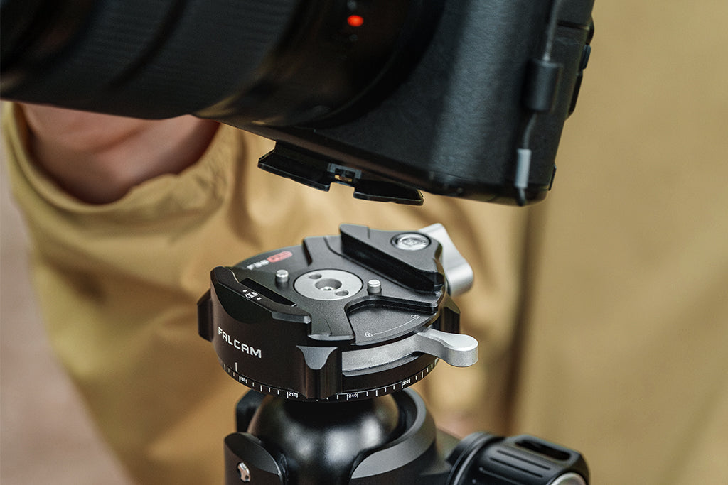
Immediately after mounting your gear, perform a "Tug Test." Don't just trust the click of the quick-release. Give the camera a firm pull in the opposite direction of the mount. According to the ISO 1222:2010 Photography — Tripod Connections standard, screw connections must maintain integrity under specific torque. If there is any "mushiness" during the tug, your fasteners or the internal joint structure may be fatigued.
The Biomechanics of Failure: Why Your Wrist is Killing Your Rig
Here is a non-obvious insight: your rig isn't just failing because of the camera's weight; it's failing because of leverage.
When you extend a monitor on a magic arm or use a long extension pole, you are creating a massive "lever arm." We modeled a "Heavy-Duty Prosumer" scenario to see exactly how much stress this puts on a joint.
The Math of the Handheld Rig: If you have a 2.8kg cinema rig (camera + cage + lens) held 0.35m away from the center of the joint (your wrist or a handle), the torque ($\tau$) is calculated as: $$\tau = m \times g \times L$$ $$2.8kg \times 9.81 m/s^2 \times 0.35m \approx 9.61 N\cdot m$$
Why this matters: This loading represents roughly 60-80% of the Maximum Voluntary Contraction (MVC) for an average adult. When your muscles reach this level of fatigue, you develop "micro-tremors." These high-frequency vibrations are transferred directly into the aluminum joints.
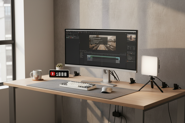
Our modeling shows that while aluminum ball heads have a natural resonance of ~15Hz, they have very low damping. This means those micro-tremors stay in the metal, accelerating the formation of stress fractures. This is why we often recommend moving heavy accessories like monitors or large mics to lighter, dedicated mounting systems (like the F22 ecosystem) to reduce that leverage. Eliminating the Shake is as much about protecting your hardware as it is about getting a steady shot.
The Over-Tightening Trap
One of the most common mistakes I see—even among pros—is over-tightening quick-release levers.
There is a psychological urge to "crank it down" for safety. However, over-tightening doesn't actually increase the holding power beyond the designed clamp force. Instead, it dramatically accelerates wear on the internal cam mechanism and can initiate cracks in the lever's pivot pin.
The Rule of Thumb: Tighten until the lever is firm, but if you have to use the ball of your hand to force it shut, you're likely exceeding the material's elastic limit. You're not making it safer; you're making it brittle.
Environmental Killers: UV and Thermal Shock
While aluminum fails via fatigue, Carbon Fiber and plastic joints have a different enemy: the environment.
1. UV Degradation
For carbon-fiber-reinforced plastic joints, UV degradation is a silent killer. If you store your rig in a hot car or leave it in direct sunlight for days, the resin becomes brittle. Unlike aluminum, which "clicks," a UV-damaged plastic joint will fail catastrophically with no visible warning.
2. The "Thermal Bridge" (Winter Warning)
Aluminum is a fantastic thermal conductor. In extreme cold, your quick-release plates act as a "thermal bridge," sucking heat out of your camera body and battery. This can cause the metal to contract at a different rate than the camera’s magnesium chassis, creating "thermal stress" at the mounting point.
- Pro Tip: Attach your aluminum plates to your cameras indoors before heading out into the cold. This allows the materials to settle and reduces the risk of the screw loosening due to thermal contraction.
Workflow ROI: The Hidden Cost of Bad Joints
Maintaining your rig isn't just about safety; it's about the bottom line. Let's look at the "Workflow ROI" of using a reliable, fast-swapping system versus traditional threaded mounts.
- Traditional Thread Mounting: ~40 seconds per swap.
- Modern Quick Release (e.g., F38/F22): ~3 seconds per swap.
If you’re a pro doing 60 swaps per shoot and you shoot 80 days a year, that’s roughly 49 hours saved annually. At a professional rate of $120/hr, that's over $5,900 in recovered time.
But that ROI vanishes the moment a $100 joint fails and drops a $5,000 camera. This is why we advocate for the "50-Hour Rule": inspect all load-bearing joints with magnification every 50 hours of active use, or after any significant impact.
The Pre-Shoot Safety Checklist
Before you head out, run through this 30-second protocol to ensure your rig joints are "Zero-Fail" ready:
- Audible: Listen for any "clicks" or "ticks" when adjusting ball heads.
- Tactile: Perform the "Tug Test" on all quick-release plates.
- Visual: Check for the "Orange/Silver" locking indicators. Ensure the locking pin is fully engaged.
- Cable Check: Ensure heavy HDMI or power cables aren't creating unwanted torque on your mounts. Use cable clamps to provide strain relief and Maintain Structural Integrity.
Summary of Material Inspection
| Component Type | Look For... | Listen For... | Frequency |
|---|---|---|---|
| Aluminum Ball Heads | Hairline cracks near pivot | Sharp "clicking" sound | Every 50 Hours |
| Quick Release Plates | Rounded teeth / scoring | Gritty feeling when sliding | Every Shoot |
| Carbon Fiber Legs | Fraying or "cloudy" resin | Cracking/Splintering sound | Monthly |
| Plastic Knobs | Whitening (stress marks) | Stripping (smooth rotation) | Every Shoot |
Final Thoughts: Be a Pro-Active Rigger
Your rig is the bridge between your vision and the sensor. Don't let a microscopic crack stand in the way of a masterpiece. By understanding the biomechanics of torque and the science of material fatigue, you can spot failures before they become catastrophes.
Remember: A "click" is a warning. A "crack" is a stop sign. Stay safe out there, and keep your gear tight.
Method & Assumptions (How we modeled this)
Our analysis of prosumer rig failure uses a deterministic scenario model to estimate stress levels. This is a scenario model, not a controlled lab study.
| Parameter | Value | Unit | Rationale |
|---|---|---|---|
| Rig Mass | 2.8 | kg | Full-frame cinema setup (Camera + Lens + Cage) |
| Lever Arm (L) | 0.35 | m | Distance from handle/wrist to center of gravity |
| Natural Frequency | 15 | Hz | Typical resonance for aluminum ball head joints |
| Damping Ratio | 0.008 | fraction | Standard damping for machined aluminum 6061 |
| MVC Limit | 10 | N·m | Lower bound for human wrist torque capacity |
Boundary Conditions:
- Linear Damping: The model assumes linear vibration decay; actual joints may have non-linear friction.
- Static Torque: Calculations assume a horizontal hold (max moment). Dynamic movement (swinging) will increase these loads significantly.
- Material Uniformity: Assumes no prior manufacturing defects in the 6061 aluminum.
Disclaimer: This article is for informational purposes only. Hardware maintenance involves inherent risks to equipment. Always consult your manufacturer’s manual for specific load ratings and maintenance protocols. The author and publisher are not responsible for gear damage resulting from the use of these techniques.
Sources & Citations
- ISO 1222:2010 Photography — Tripod Connections
- The 2026 Creator Infrastructure Report: Engineering Standards & Workflow Compliance
- A study on the combined effect of notch and fretting on the fatigue life behaviour of Al 7075-T6
- Small Fatigue Cracks in Aluminum Alloys
- NIOSH: Elements of Ergonomics Programs (Wrist Torque Risk Factors)