The Stability-Mass Paradox in High-Altitude Imaging
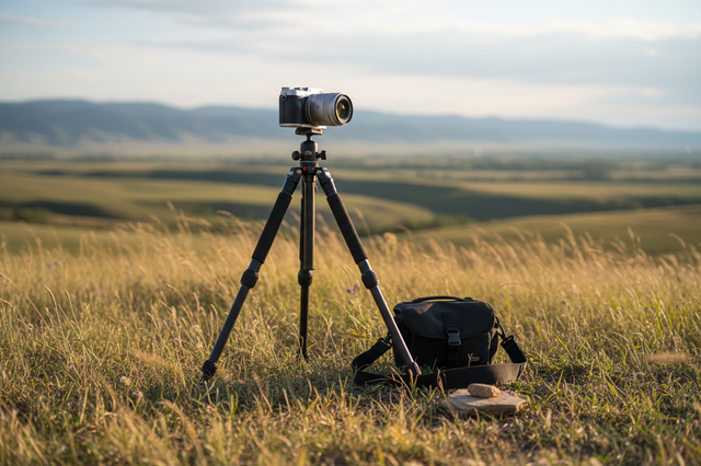
For the elite solo creator, the ridge-line represents the ultimate architectural challenge. It is an environment where the "Lightweight is Right" philosophy of mountaineering crashes into the "Mass is Stability" physics of traditional cinematography. In the thin air of high-altitude expeditions, every gram of equipment is a tax on the creator’s metabolic ceiling. However, as mass is stripped away to facilitate the ascent, the resulting ultra-low-mass gear becomes increasingly susceptible to aerodynamic interference.
This phenomenon, often categorized as "Ridge-Line Rigging," refers to the strategic management of wind drag and vibration on lightweight support systems in exposed environments. It is a critical frontier in creator infrastructure. When a carbon fiber tripod is placed on a wind-swept col, it no longer acts merely as a static support; it becomes a sail, a resonator, and a lever. Understanding the fluid dynamics at play is essential for ensuring that a $10,000 camera system remains secure when the dynamic load of a 50 kph gust strikes the rig.
Aerodynamic Drag and the "Singing" Leg Profile
The primary adversary on an exposed ridge is not the static weight of the camera, but the dynamic pressure of the wind. According to the Engineering ToolBox, wind load increases with the square of the wind speed. This means a gust of 40 kph exerts four times the force of a 20 kph breeze.
For lightweight tripod legs, the drag coefficient ($C_d$) is largely determined by the cross-sectional profile. While cylindrical legs are standard, they are prone to a phenomenon known as von Kármán vortex shedding. As wind flows around the leg, it creates alternating low-pressure vortices. If the frequency of this shedding matches the natural resonant frequency of the carbon fiber leg, the tripod will begin to "sing" or vibrate intensely.
The Matte vs. Glossy Heuristic
Based on patterns observed in high-altitude filming and simplified aerodynamic modeling, the surface finish of carbon fiber can play a non-obvious role in stability. A matte or slightly textured finish may disrupt the boundary layer of air more effectively than a high-gloss coat. This disruption can transition the flow from laminar to turbulent earlier, potentially reducing the organized "pulse" of vortex shedding and minimizing wind-induced vibration.
Logic Summary: This discussion assumes a standard cylindrical leg profile with characteristic diameter on the order of typical carbon tripod legs, at Reynolds numbers ($Re$) associated with roughly 20–60 kph crosswinds. The qualitative idea that surface roughness can trip a boundary layer to turbulence and alter drag comes from general aerodynamics; here it is used as a rigging heuristic, not a lab-verified prescription for a specific tripod model.

Structural Mechanics: The Center Column as a Lever
In a laboratory setting, a center column provides convenient height adjustment. In a ridge-line scenario, it is often the single greatest point of failure. From a mechanical engineering perspective, an extended center column acts as a lever arm. Any wind force hitting the camera body is amplified by the length of the column, exerting massive torque on the tripod apex.
Experienced mountaineers and solo creators frequently adopt the "Zero-Column Policy" for high-wind environments. By removing the center column entirely and mounting the head directly to the tripod spider, the creator lowers the center of gravity and eliminates the longest vibration-amplifying lever in the system.
The 10kph Capacity Rule (Heuristic Only)
Rigging for dynamic environments requires a departure from static load ratings. While a tripod head might be rated for 10kg, that rating rarely accounts for the lateral force of a storm. A practical rule-of-thumb used in alpine imaging suggests that for every 10 kph increase in wind speed, the recommended minimum load capacity for the tripod head should scale aggressively to compensate for dynamic loads.
| Wind Speed (kph) | Effective Dynamic Load Multiplier | Recommended Head Capacity (for 2kg Rig) |
|---|---|---|
| 0 (Static) | 1.0x | 2 kg |
| 10 | 2.0x | 4 kg |
| 20 | 4.0x | 8 kg |
| 30 | 8.0x | 16 kg |
| 40+ | 16.0x+ | Extreme/Specialized Rigging |
Heuristic, not a safety standard: This "10kph Capacity Rule" is an experience-based planning heuristic for image stability and handling margin, not a structural failure threshold or a guarantee of safety. Always stay within the manufacturer’s official load limits and treat this table as a conservative guide for choosing a stiffer, more overbuilt head when you expect higher winds.
How the Heuristic Relates to the Physics
You can sanity-check the rule using a very simplified side-load model:
- Approximate lateral wind force on the rig as $F \approx \tfrac{1}{2} \rho C_d A v^2$.
- Treat the center column plus head as a cantilever arm with length $L$.
- The overturning or bending moment at the tripod apex is then roughly $M \approx F \times L$.
If you double wind speed, $v^2$ — and thus $F$ — increases by a factor of four. In practice, creators also add safety factors for gusts, imperfect leg placement, and flex in the system. The doubling-per-10kph heuristic bakes in these extra margins rather than claiming an exact mechanical law.
Simple Field Test for Head Stability
To avoid relying on theory alone, you can do a quick, controlled test before a big trip:
- Load the head: Mount your typical rig (camera, lens, accessories) on the tripod head at the working height you use most often.
- Apply a side load: Indoors or in mild wind, gently push the rig sideways at the camera body with a steady hand to simulate a gust. Avoid jerky impacts.
-
Observe the motion: Let go and watch how the system behaves:
- If the rig creeps back slowly with minimal oscillation, the head and legs are relatively stiff.
- If it bounces and “rings” several times before settling, or if you see visible flex at the head, you are operating close to the dynamic comfort limit for that setup.
- Increase the margin: To improve head stability, lower the center column, shorten leg extensions, reduce rig mass, or move to a higher-capacity head.
This kind of test does not replicate storm conditions, but it gives you a feel for how much dynamic margin your rig has before you expose it on a ridge.
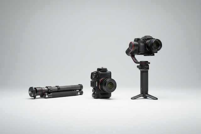
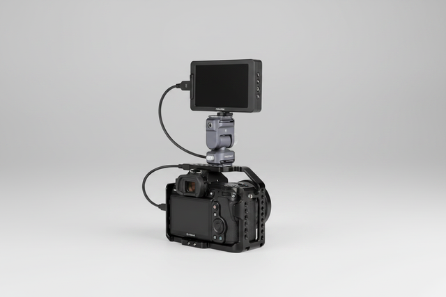
Biomechanical Efficiency: The Wrist Torque Analysis
In remote solo expeditions, the "infrastructure" isn't just the gear; it is the creator’s body. Every mechanical inefficiency in the rigging system translates to physical fatigue. This is most evident when using handheld or "run-and-gun" setups where accessories are poorly balanced.
The physics of "Wrist Torque" helps explain why modular, low-profile interfaces are often superior for long-duration expeditions. We can model the strain on a creator's wrist using the formula: $$\tau = m \times g \times L$$ Where $\tau$ is torque, $m$ is the mass of the rig, $g$ is gravity, and $L$ is the lever arm (the distance from the wrist to the rig's center of mass).
Consider a 2.8kg cinema rig. If the monitor and microphone are mounted high and forward, increasing the lever arm to 0.35m, the resulting torque is approximately $9.61 N\cdot m$. For many adults, loads of this order can represent a substantial fraction of their Maximum Voluntary Contraction (MVC), leading to rapid muscle fatigue and "shaky cam." By utilizing ultra-low-profile quick-release systems to bring accessories closer to the center of gravity, creators can reduce $L$, significantly lowering the perceived weight and metabolic cost of the shoot.
Workflow ROI: The Economics of Quick Release
In extreme environments, time is more than money; it is safety. Fumbling with traditional 1/4"-20 threads while wearing gloves in sub-zero temperatures is a liability. The shift toward ecosystem-wide quick-release standards—such as those discussed in The 2026 Creator Infrastructure Report—is driven by quantifiable workflow gains.
The Annual Time-Value Calculation
If we compare a traditional thread-mounting workflow (~40 seconds per swap) to a modern modular quick-release interface (~3 seconds per swap), the cumulative impact is significant for a professional.
| Metric | Traditional Threading | Modular Quick Release |
|---|---|---|
| Time per Swap | 40 seconds | 3 seconds |
| Swaps per Shoot (Avg) | 60 | 60 |
| Time spent swapping/shoot | 40 minutes | 3 minutes |
| Annual Time Cost (80 shoots) | ~53 Hours | ~4 Hours |
By reclaiming nearly 49 hours of "fumble time" annually, the creator gains over an entire work week of productive shooting or rest.
Example assumption: If you value your time at an illustrative rate of $120/hour, the 49 hours saved correspond to about $5,800/year in time value. To adapt this to your situation, use:
[ \text{Annual Value} = \text{Annual Hours Saved} \times \text{Your Hourly Rate} ]
or simply treat "~49 hours per year" as a non-monetary benchmark of reclaimed time.
Practical Ridge-Line Workflows
The Pre-Shoot Safety Checklist
Trust in load-bearing gear is built on verification. Before committing a camera to a ridge-line rig, creators can follow a three-point tactile protocol:
- Audible: Listen for the distinct mechanical "Click" of the locking interface.
- Tactile: Perform a "Tug Test" (Pull-Test) along the axis of the mount to ensure the locking pin is fully engaged.
- Visual: Verify the status of the safety lock (often indicated by a color-coded slider).
Thermal Shock and the Aluminum Bridge
Most professional quick-release plates are precision-machined from 6061 or 7075 Aluminum Alloy. While these materials offer high rigidity and tight tolerances, they also act as thermal bridges. In extreme cold, an aluminum plate will rapidly conduct heat away from the camera's battery compartment.
Expert Tip: Attach your aluminum mounting plates to the camera body while still in a warm environment (tent or vehicle). This helps prevent sudden "thermal shock" to the camera base and slows the initial rate of battery cooling when you step onto the exposed ridge.
Field Quick-Diagnosis for Vibration and Vortex Shedding
When you’re already on the ridge, you often need to decide in seconds whether a rig is safe enough to run. These simple checks help connect the theory to what you actually see and hear:
-
Ribbon or Cord Test (Vortex Frequency Clue)
- Tie a short length of light ribbon, tape flag, or paracord tail to one tripod leg at camera height.
- Watch the flapping pattern from a safe position.
- If the ribbon snaps back and forth at a steady, narrow-band rhythm and your tripod leg “sings” at the same rate, you may be close to a vortex-shedding resonance.
-
Finger-on-Leg Check (Amplitude Feel)
- Lightly rest two fingers on a tripod leg while the rig is exposed to wind.
- A faint, broad “buzz” that varies with gusts usually indicates general turbulence.
- A strong, steady vibration at a single frequency suggests you’re near a structural resonance; lower the center column, rotate the rig slightly relative to the wind, or add damping (e.g., carefully hang a small pack) to break the pattern.
-
Phone Accelerometer Snapshot (Basic Measurement)
- Many smartphones include an accelerometer readout via built-in diagnostics or simple apps.
- Strap or tape the phone to the center column (or clamp it with a phone holder) and record a short sample in gusty wind.
- Compare peak vibration between small changes (column extended vs. fully down, legs narrower vs. wide). Even without formal units, you can see which configuration produces visibly lower peaks and choose that setup.
These quick diagnostics are not laboratory measurements, but they give you a repeatable way to see whether a configuration change actually reduces motion before you put your most expensive glass on the rig.
Modeling Note: Methods and Assumptions
The insights presented in this article are derived from a deterministic parameterized model of wind-load and biomechanical stress, combined with field experience in exposed, high-wind shooting. This is a scenario model intended for planning and gear selection, not a controlled laboratory study.
| Parameter | Value or Range | Unit | Rationale |
|---|---|---|---|
| Wind Speed ($v$) | 10–60 | kph | Representative crosswind range for alpine ridges |
| Air Density ($\rho$) | 0.9–1.1 | $kg/m^3$ | Approximate range from high-altitude (~3000m) to denser air, used for order-of-magnitude planning |
| Drag Coefficient ($C_d$) | 1.0–1.2 | - | Typical order-of-magnitude range for a smooth, cylindrical tripod leg in crossflow; treated here as an engineering estimate, not a measurement for a specific product |
| Rig Mass ($m$) | 1.5–4.0 | kg | Professional mirrorless/cinema rig range |
| Lever Arm ($L$) | 0.1–0.4 | m | Variance in handheld vs. offset rigging |
Scope and limits: The $C_d$ and $\rho$ ranges above are used to build intuition and rough comparisons between setups. Exact values depend on leg diameter, profile, surface finish, and specific altitude and temperature. For very high winds, very large legs, or non-cylindrical profiles, you should not treat these numbers as design limits—only as planning inputs.
Boundary Conditions
- Substrate Variance: These calculations assume solid ground. In deep snow, the use of specialized snow baskets is recommended, as standard sand baskets can create a "suction" effect that destabilizes the legs during gust resets.
- Mechanical Wear: Load ratings assume interfaces are free of grit and ice. Regular maintenance of the ISO 1222:2010 compliant connections is important for high-altitude reliability.
By mastering the aerodynamics of their support systems and the biomechanics of their rigs, the elite solo creator can transform the ridge-line from a place of risk into a world-class studio. The future of adventure imaging lies in this intersection of engineering discipline and creative endurance.
Disclaimer: High-altitude mountaineering and filming in extreme weather conditions involve inherent risks to life and equipment. This article is for informational purposes only and does not constitute professional safety or engineering advice. Always consult with a certified mountain guide and perform independent gear stress tests before attempting high-risk expeditions.