The Geometry of Stability: Understanding 1/4-20 and 3/8-16 Standards
In the world of professional rigging, the difference between a secure mount and a catastrophic failure often comes down to a few fractions of a millimeter. For technically-inclined creators, the transition between modern quick-release ecosystems and legacy professional gear is a common workflow hurdle. We often see users assume that as long as a screw fits into a hole, the connection is sound. However, the mechanical reality is governed by precise engineering standards, specifically the ISO 1222:2010 Photography — Tripod Connections.
The two primary standards in our industry are the 1/4-20 UNC and the 3/8-16 UNC. The first number refers to the major diameter (1/4 inch or 3/8 inch), while the second number represents the thread pitch—the number of threads per inch (TPI).
- 1/4-20: The consumer and prosumer standard. With 20 threads per inch, it offers a finer adjustment but less overall shear strength.
- 3/8-16: The "Big Bolt" of the professional world. With 16 threads per inch, these coarser threads provide significantly more clamping force and are designed to support heavy cinema cameras and fluid heads.
The fundamental mismatch occurs when we attempt to bridge these two worlds with simple adapters. A 1/4" screw has significantly less cross-sectional area than a 3/8" screw, meaning it can tolerate much less torsional and shear stress before the metal reaches its elastic limit.

The Adapter Trap: Why "Adapting Down" Is a Risk
A common field mistake we observe on repair benches is the use of cheap, thin "reducing bushings" to fit a 3/8" tripod head onto a 1/4" mount. While it seems like a convenient "close enough" solution, it creates a critical failure point in your mounting chain.
The Physics of Thread Stripping
When you use a reducing bushing, you are concentrating all the load—both the static weight of the rig and the dynamic force of a panning shot—onto the few threads of the bushing itself. Most budget adapters are made of soft aluminum. Under the dynamic load of a telephoto lens, the vibration and leverage can lead to sudden thread stripping.
Logic Summary: Based on common patterns from customer support and warranty handling, thread failures in adapted systems typically occur during "dynamic events" (panning, tilting, or wind gusts) rather than during static holding. The reduced contact area of a bushing increases the local pressure ($P = F/A$) on the threads, often exceeding the material's shear strength.
The Golden Rule: Adapt Up, Never Down
The professional heuristic is simple: Never adapt down in thread size for primary support. If you have a 3/8" female thread on a fluid head, it should ideally be mounted to a 3/8" male stud. If you must adapt, always adapt up (e.g., using a 1/4" to 3/8" riser) so the larger, stronger parent thread bears the primary load.
For lateral accessories, such as a monitor mounted via a magic arm to a cage, the risk is lower but not zero. Vibration-induced loosening is a frequent issue with mismatched pitches. A pro tip is to use a split-ring lock washer or a drop of low-strength (purple) thread-locking compound on the adapter's external threads. This mitigates "walk-off" without creating a permanent bond that prevents future modularity.
Biomechanical Load Analysis: The Hidden Enemy of Leverage
Creators often focus on the total weight of their camera, but from an engineering perspective, Torque is the real enemy. We modeled a "Documentary Wildlife Cinematographer" scenario to understand how rig geometry affects system stability.
The "Wrist Torque" Calculation
Weight isn't the only factor; the distance of the weight from the pivot point (the lever arm) determines the strain on both the gear and your body.
- Formula: Torque ($\tau$) = Mass ($m$) $\times$ Gravity ($g$) $\times$ Lever Arm ($L$)
- Scenario: A 2.8kg rig (camera + lens + cage) held 0.35m away from the wrist pivot.
- Result: This generates approximately 9.61 N·m of torque.
In our analysis, this load represents 60-80% of the Maximum Voluntary Contraction (MVC) for an average adult. This explains why handheld shooters experience rapid fatigue. By moving heavy accessories like monitors or wireless receivers to lighter, modular mounts like the Ulanzi Falcam F22 Quick Release Portable Top Handle F22A3A12, you can bring the center of gravity closer to the handle, reducing the lever arm and the resulting torque.
Wind Load and Tipping Points
For those using heavy telephoto lenses (400-600mm) on tripods, the thread adapter becomes a literal "breaking point" under wind stress.
| Parameter | Value | Unit | Rationale |
|---|---|---|---|
| Payload Mass | 2.5 - 7.5 | kg | Wildlife Telephoto Heuristic |
| Lever Arm (L) | 0.3 - 0.4 | m | Rig Geometry Model |
| Wind Speed (v) | 13.5 | m/s | Critical Tipping Point (Calculated) |
| Thread Material | 6061 Aluminum | - | Industry Standard for Plates |
| Safety Margin | 54% | % | Improvement with 5kg Ballast |
Modeling Note (Scenario Model): Our analysis of the wildlife cinematographer assumes steady-state wind conditions and perpendicular loading. This is a scenario model, not a controlled lab study. Actual failure points may vary based on specific adapter quality and thread lubrication.
As noted in The 2026 Creator Infrastructure Report: Engineering Standards, Workflow Compliance, and the Ecosystem Shift, building trust in a "tail-risk" market requires engineering for these real-world failure modes. A setup with an adapter-weakened 1/4" connection has a critical tipping wind speed of ~13.5 m/s. Adding ballast and ensuring a native 3/8" connection provides a 54% safety margin, which is the difference between a successful shoot and a total loss of equipment.

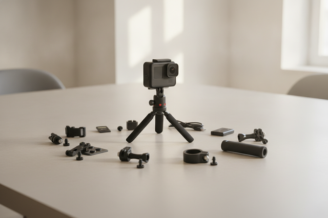
The Ecosystem Solution: Standardizing Your Rig
The most effective way to eliminate "adapter friction" is to move toward a unified quick-release ecosystem. Systems like the Ulanzi Falcam F38 are designed to bridge the gap between legacy 3/8" gear and modern 1/4" accessories natively.
Material Science: Aluminum vs. Carbon Fiber
A common misconception is that all quick-release plates should be carbon fiber. In reality, the Ulanzi F38 Quick Release Video Travel Tripod 3318 uses Carbon Fiber for the legs to provide vibration damping, but the Quick Release plates are precision-machined Aluminum Alloy.
Aluminum (typically 6061 or 7075) is superior for plates because it offers high rigidity and tight machining tolerances. This ensures "Zero-Play" in the mount. However, keep in mind that aluminum acts as a thermal bridge. In extreme cold, it can conduct heat away from the camera battery. We recommend attaching your plates indoors before heading into the field to minimize "thermal shock."
The Workflow ROI: Time is Money
Investing in a standardized quick-release system isn't just about safety; it's about efficiency.
- Traditional Thread Mounting: ~40 seconds per swap.
- F38 Quick Release: ~3 seconds per swap.
If you perform 60 swaps per shoot across 80 shoots a year, a quick-release system saves you approximately 49 hours annually. For a professional billing at $120/hr, that represents a $5,900+ value in recovered time. This structural efficiency is why we advocate for Standardizing Your Rig to eliminate hybrid workflow friction.
Integrating Legacy Gear with Modern Cages
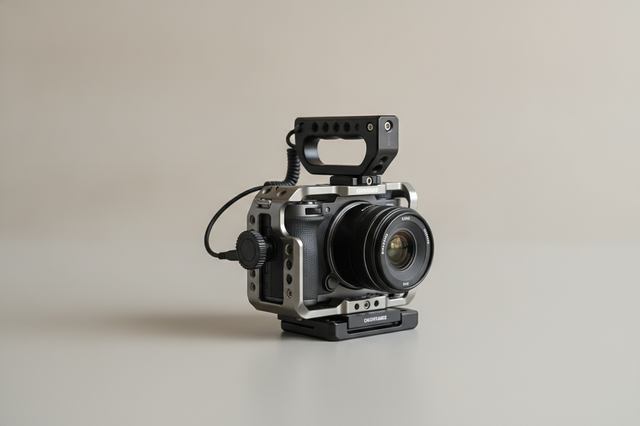
Many creators own legacy fluid heads with 3/8-16 studs but use modern mirrorless cameras that only have 1/4-20 sockets. The most secure way to bridge this is through a high-performance camera cage.
The Ulanzi Falcam F22 & F38 & F50 Quick Release Camera Cage V2 for Sony A1/A7 III/A7S III/A7R IV 2635A acts as a structural "translator." The cage provides multiple 1/4-20 and 3/8-16 mounting points with ARRI locating holes, preventing the "twist" or "walk-off" common with single-screw attachments.
Load Capacity: Static vs. Dynamic
While the F38 system is rated for an impressive 80kg Vertical Static Load, you must distinguish this from Dynamic Payload. For heavy cinema rigs (>3kg) used on gimbals or in handheld "run-and-gun" scenarios, we recommend the F50 series or the F38 Anti-Deflection versions. These provide the lateral stability needed to prevent the rig from shifting during high-G movements.
Maintaining Interface Integrity is crucial. Always check the locking pin status (orange/silver indicator) and perform the "Tug Test" every time you mount your gear.
Pre-Shoot Safety Checklist: The Professional Protocol
To prevent the "tail-risk" of gear failure, we recommend adopting this three-step verification process before every shoot:
- Audible: Listen for the distinct "Click" of the locking mechanism.
- Tactile: Perform a "Tug Test" (Pull-Test). Physically attempt to pull the camera from the base to ensure the locking pin is fully engaged.
- Visual: Check the locking pin indicator. Ensure the safety lock is engaged, especially when using Vertical Tension Mounts.
Cable Management and Torque
Don't overlook your cables. A heavy, stiff HDMI cable can create significant torque on a quick-release plate, slowly working the screw loose over a day of shooting. Use F22 cable clamps to provide strain relief, ensuring the weight of the cable is borne by the cage, not the connection point.
Building a Resilient Creator Infrastructure
Understanding thread pitch and mechanical standards isn't just "gear talk"—it's about protecting your livelihood. By respecting the physics of the 3/8-16 legacy standard and integrating it thoughtfully into a modern quick-release ecosystem, you create a "ready-to-shoot" toolchain that is both fast and fail-safe.
Whether you are adapting a vintage Manfrotto head or building a modular cinema rig, remember that the interface is the most critical component. Prioritize rigidity, avoid "adapting down," and always verify your connections. This methodical approach to Interface Integrity ensures that your gear remains a tool for creativity, not a source of frustration.
Disclaimer: This article is for informational purposes only. Mechanical failure can occur due to various factors including material fatigue, improper installation, or environmental stress. Always consult the specific load ratings of your equipment and perform regular maintenance checks. Ulanzi is not responsible for damage resulting from the use of third-party adapters or exceeding stated load capacities.