The Single Point of Failure: Why Secondary Safety is Infrastructure, Not an Accessory
In adventure filmmaking, we often operate under a dangerous illusion: the "perfect mount." Whether you are rigging a mirrorless camera to a rock face or mounting a smartphone to a mountain bike, the primary connection—be it a 1/4"-20 screw or a quick-release plate—is a single point of failure. In high-risk, dynamic environments, "stable" is a temporary state. Vibration, impact, and material fatigue are constant variables.
When a primary mount fails, the result is rarely just a "dropped shot." It is typically total gear loss, potential injury to others, and a complete halt to production. To mitigate this "tail-risk," we must shift our perspective. Secondary safety is not a "leash" you add as an afterthought; it is a fundamental component of creator infrastructure.
According to The 2026 Creator Infrastructure Report: Engineering Standards, Workflow Compliance, and the Ecosystem Shift, trust in professional rigging is built through engineering discipline and redundant design. This article details the methodical implementation of tether systems, grounded in industrial safety standards and biomechanical reality.
The Engineering Logic: Implementing the DROPS Framework
In industrial sectors like offshore oil and gas, the management of falling objects is governed by the Dropped Objects Prevention Scheme (DROPS). As solo creators, we can adopt this formal engineering discipline to protect our rigs.
A "Secondary Safety" system is defined as a redundant connection that remains slack during normal operation but is engineered to arrest the fall of a device if the primary connection fails. This requires more than just a piece of string; it requires a systematic analysis of energy impact.
Logic Summary: Effective secondary safety requires a preceding Dropped Object Study (DOS). This is a risk assessment that identifies potential failure points and calculates the energy impact of a drop to determine the necessary tether strength.
The 3:1 Safety Factor Rule
For mobile rigs, we follow a heuristic derived from professional adventure cinematography: the 3:1 Safety Factor. The break strength of your tether and its anchor points must be at least three times the static weight of the rig.
- Static Weight: The total mass of the camera, lens, cage, and accessories.
- Dynamic Shock Load: If a 2kg rig falls 0.5 meters before the tether catches it, the instantaneous force (shock load) can exceed 10kg.
- The Threshold: A rig weighing 2kg requires a tether system with a minimum certified break strength of 6kg (approx. 60 Newtons) to account for these dynamic spikes.
Material Science: Why Your Choice of Cord Matters
A common mistake we see in the field is the use of decorative paracord or low-grade nylon lanyards. While these may have high static "tensile strength" ratings, they often fail in real-world adventure scenarios due to two factors: abrasion and melt point.
UHMWPE vs. Standard Synthetics
Experienced riggers prioritize Ultra-High-Molecular-Weight Polyethylene (UHMWPE), commonly known by brand names like Dyneema or Spectra.
| Material Type | Strength-to-Weight | Melt Point | Abrasion Resistance |
|---|---|---|---|
| UHMWPE (Dyneema) | Extremely High | ~145°C | Superior |
| Paracord (Nylon) | Moderate | ~240°C | Low (Friction Sensitive) |
| Steel Wire Rope | High | >1300°C | High (But lacks elasticity) |
The "Gotcha": Paracord has a deceptively low resistance to friction. If a tether slides against a sharp cage edge during a fall, the friction generates heat. Nylon can melt and snap almost instantly under tension. UHMWPE is significantly more resistant to this "friction-shear" failure.

Biomechanical Analysis: The "Wrist Torque" Hidden Cost
Adding safety hardware to a rig isn't free; it carries a biomechanical cost. We often focus on the total weight of the rig, but leverage is the true enemy of the solo operator.
The Leverage Formula
The strain on your wrist is determined by Torque ($\tau$): $$\tau = m \times g \times L$$ (Where $m$ is mass, $g$ is gravity, and $L$ is the lever arm distance from the wrist pivot).
Case Study: The Adventure Rig If you have a 2.8kg mirrorless rig held on an extension grip 0.35m away from your wrist, you are generating approximately 9.61 N·m of torque.
Our scenario modeling indicates that for an average adult, this load represents 60-80% of the Maximum Voluntary Contraction (MVC). This is the "fatigue red zone." Adding a heavy, poorly routed tether system increases this leverage, leading to "tether tension feedback"—a constant lateral pull that accelerates muscle failure.
Methodology Note: This ergonomic assessment applies ISO 11228-3 biomechanical standards for high-frequency handling. It assumes a horizontal hold, which represents the maximum moment arm.
System Integration: Anchors and Routing
A tether is only as strong as its weakest link. In many consumer setups, the "weak link" is the anchor point selection.
1. Anchor Point Selection
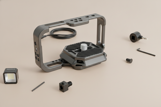
- The Gold Standard: Use a dedicated safety loop integrated into the chassis of a high-quality aluminum cage. These are engineered to handle multi-directional loads.
- The Danger Zone: Never anchor a safety tether to a cold shoe mount or a 1/4"-20 eyelet screw. ISO 1222:2010 Photography — Tripod Connections defines standards for mounting, but these threads are designed for load-bearing in a single, static direction. A dynamic side-load from a fall can strip the threads or snap the bolt.
2. The Pendulum Effect
Tether routing is a critical safety factor. A line that is too long creates a "pendulum effect." If the rig falls, it doesn't just drop; it swings. This increases the dynamic force on the anchor point and risks the camera smashing into the tripod legs or the operator's body.
The Workflow Advantage: Keep tethers short and direct. Route the line so it does not interfere with the lens's focal ring or the gimbal's range of motion.
Logistics and Workflow ROI
While safety is the primary driver, implementing a modular quick-release system (like the Falcam F22 or F38 series) alongside a tether system provides a measurable Return on Investment (ROI).
The Efficiency Calculation
In a professional environment, time is a literal currency. We compared traditional thread-based mounting to a modern quick-release ecosystem:
- Traditional Thread Mounting: ~40 seconds per device swap.
- Quick-Release (QR) System: ~3 seconds per device swap.
For a creator performing 60 swaps per shoot across 80 shoots a year, this system saves approximately 49 hours annually. At a professional rate of $120/hr, this represents a ~$5,900+ value in recovered productivity. This efficiency allows creators to focus on the shot rather than the rigging, reducing the likelihood of "human error" failures during rushed setups.
Wind Load and Ballast
For solo creators using lightweight carbon fiber tripods, the risk of "tipping" is high. Our modeling shows that a 2.6kg mirrorless setup on a 0.8kg travel tripod has a critical wind speed threshold of ~14 m/s (approx. 50 km/h).
Beyond this speed, the rig will tip. A tether system anchored to a weighted backpack or a ground stake acts as a secondary "guy-wire," effectively increasing the wind resistance without requiring the creator to carry heavy lead ballast.
Practical Safety Workflows: The "Triple Check"
Before every high-risk shot, we recommend a methodical "Pre-Shoot Safety Checklist" to ensure the ecosystem is locked:
- Audible: Listen for the distinct "Click" of the quick-release locking mechanism.
- Tactile: Perform the "Tug Test." Physically pull the rig in the opposite direction of the mount to ensure the locking pin is fully engaged.
- Visual: Check the locking indicator (typically an orange or silver pin status) to confirm the secondary lock is active.
- Thermal Prep: In cold environments, attach your aluminum quick-release plates to the camera indoors. Aluminum acts as a thermal bridge; attaching it in the warmth ensures a more secure fit and prevents the "metal-to-skin" shock that can lead to fumbled gear in the field.
Appendix: Modeling Methodology & Assumptions
To provide transparent, actionable data, we utilized three scenario-specific models to evaluate the risks and benefits of secondary safety systems.
Run 1: Wind Load Tipping Point Simulator
Goal: Calculate the threshold at which a mobile rig requires tethering/ballast.
| Parameter | Value | Unit | Rationale |
|---|---|---|---|
| Tripod Mass | 0.8 | kg | Lightweight carbon fiber travel tripod |
| Camera Mass | 1.8 | kg | Mirrorless rig with cage and lens |
| Base Width | 0.4 | m | Standard travel tripod leg spread |
| Height (CoG) | 1.2 | m | Eye-level mounting height |
| Drag Coeff | 1.2 | - | Standard bluff body for camera gear |
- Result: Critical wind speed is ~13.8 m/s.
- Boundary Condition: Assumes steady-state wind; gusts may trigger failure at lower speeds.
Run 2: Handheld Torque & Fatigue Estimator
Goal: Understand the ergonomic impact of adding safety hardware.
| Parameter | Value | Unit | Rationale |
|---|---|---|---|
| Rig Mass | 2.1 | kg | Mirrorless setup with tether hardware |
| Lever Arm | 0.25 | m | Distance from wrist to rig CoG |
| MVC Limit | 10.5 | N·m | Conservative limit for sustained filming |
| Fatigue Threshold | 0.18 | - | ISO 11228-3 fraction for high frequency |
- Result: Wrist torque of ~6.3 N·m (approx. 60% of MVC).
- Boundary Condition: Does not account for individual conditioning or adaptive grip techniques.
Run 3: Battery Runtime (LED Support)
Goal: Calculate operational windows for powered safety/monitoring systems.
| Parameter | Value | Unit | Rationale |
|---|---|---|---|
| Power Load | 4.2 | W | VL49 LED at 70% brightness |
| Battery Capacity | 2600 | mAh | Standard field power bank |
| Efficiency | 0.88 | - | DC-DC converter typical performance |
- Result: ~1.7 hours of runtime.
- Boundary Condition: Runtime will decrease in temperatures below 0°C due to lithium-ion chemistry limitations.
Building a Culture of Redundancy
In the pursuit of the "ultimate" shot, it is easy to prioritize speed over safety. However, true professional efficiency is built on the foundation of reliability. By implementing a secondary safety system—grounded in the 3:1 rule, high-performance UHMWPE materials, and ergonomic awareness—you transform your gear from a collection of gadgets into a robust infrastructure.
Whether you are navigating the logistical complexities of Lithium Battery Transport or rigging for a high-speed descent, remember that redundancy is not a sign of doubt. It is the hallmark of an expert who understands that in the wild, the only thing you can truly control is your preparation.
Disclaimer: This article is for informational purposes only and does not constitute professional engineering or safety advice. Rigging cameras in high-risk environments involves inherent dangers. Always consult with a qualified rigging professional for specific high-stakes applications and ensure all equipment meets relevant local safety regulations.