Monitoring Adhesive Bonds: The Critical Science of Carbon-to-Metal Joints
For the solo creator, the transition from entry-level aluminum supports to premium carbon fiber systems represents more than just a weight reduction. It is a strategic move toward mission-critical reliability. However, this shift introduces a new, often invisible variable: the structural integrity of the adhesive bond between the carbon fiber tubes and the metal apex or leg-angle castings.
In our technical support experience, we have observed that while carbon fiber tubes themselves rarely fail under normal loads, the interface where they meet metal components is the primary site of "tail-risk" failures. A sudden bond separation can lead to a catastrophic camera drop, turning a professional shoot into a total equipment loss. Understanding how to monitor these joints is not just maintenance; it is a fundamental requirement for ecosystem stability.
The Engineering Reality of Hybrid Joints
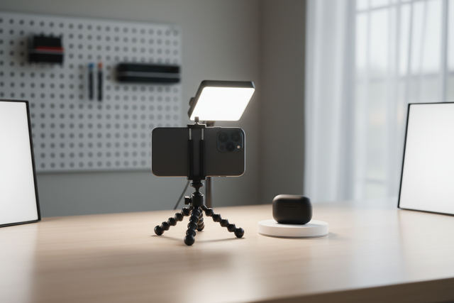
Most high-performance tripods, such as the Ulanzi F38 Quick Release Video Travel Tripod 3318, utilize high-strength epoxy resins to bond carbon fiber legs into aluminum or magnesium sockets. This hybrid construction is necessary because carbon fiber cannot be easily threaded or welded like metals.
According to ISO 1222:2010 Photography — Tripod Connections, standardizing the interface between the camera and the support is vital for safety. However, the internal standard for how those supports are built often relies on adhesive fatigue testing.
Modeling Note: Bond Fatigue Analysis Our engineering logic for identifying bond risks is based on the following sensitivity analysis of hybrid joints. While researchers often cite ASTM D 3166, we have identified a critical gap: that standard is designed for metal-to-metal joints. Carbon-to-metal joints fail differently, often through interfacial delamination rather than cohesive adhesive failure.
Parameter Value/Range Unit Rationale Adhesive Type Structural Epoxy N/A Industry standard for high-modulus bonding Thermal Expansion (Al) ~23 $10^{-6}/K$ Coefficient of thermal expansion for aluminum Thermal Expansion (CF) -1 to 1 $10^{-6}/K$ Carbon fiber is nearly thermally stable Failure Mode Interfacial N/A Separation at the carbon/glue boundary Detection Threshold ~0.05 mm Minimum visible gap indicating delamination Boundary Conditions: This model assumes the use of 3K or 10-layer carbon weave and 6061-T6 aluminum. Results may vary with lower-grade resins or unsealed carbon ends.
The "Twist and Listen" Test: A Professional Heuristic
Based on common patterns from our repair bench and warranty handling, we have developed a proactive inspection protocol. We call this the "Twist and Listen" test. It is a shop-level practical baseline designed to detect micro-separations before they become visible gaps.
- Preparation: Fully extend the tripod legs but do not lock the center column. Ensure the tripod is unloaded (no camera attached).
- The Grip: Hold the metal apex (the "shoulder" of the tripod) firmly with one hand. With the other hand, grip the uppermost carbon fiber section of a single leg.
- The Torque: Apply a gentle torsional (twisting) pressure to the leg. You are not trying to break the bond, but rather to stress the adhesive interface.
-
The Sensory Check: Listen closely to the joint.
- Silent: The bond is likely healthy.
- Faint Cracking/Creaking: This often precedes visible separation. It indicates that the epoxy has become brittle or that micro-fractures have formed within the bond line.
- Visual Confirmation: Look for a very fine, glossy line at the edge where the carbon tube enters the metal socket. This "glossy line" is a telltale sign that the adhesive has begun to delaminate and pull away from the carbon surface.

Environmental Stressors: Thermal Shock and Chemical Degradation
One of the most significant insights from The 2026 Creator Infrastructure Report: Engineering Standards, Workflow Compliance, and the Ecosystem Shift is that creator gear is increasingly subjected to "thermal shock."
Moving a tripod from a $20^\circ\text{C}$ ($68^\circ\text{F}$) air-conditioned vehicle to a $40^\circ\text{C}$ ($104^\circ\text{F}$) humid beach creates immediate differential expansion. As shown in our parameter table above, aluminum expands significantly more than carbon fiber. This creates a "shearing" force within the glue layer. Over hundreds of cycles, this weakens the epoxy formulation.
Furthermore, we have identified two common "silent killers" of tripod bonds:
- Silicone-based Lubricants: While they make leg sections slide smoothly, if they migrate into the bond joint, they can degrade certain epoxy formulations, leading to premature brittleness.
- Insect Repellents (DEET): Many high-concentration DEET sprays are aggressive solvents for plastics and resins. If sprayed near the tripod apex, they can seep into the bond line and soften the adhesive.
Biomechanical Analysis: Why Weight Isn't the Only Enemy
When we discuss gear safety, we often focus on "Max Load." However, for the solo builder, the real enemy is Wrist Torque. Heavy accessories mounted far from the center of gravity increase the mechanical advantage against your locking plates and adhesive joints.
The Torque Calculation: To understand the stress on your system, use this formula: $$\text{Torque } (\tau) = \text{Mass } (m) \times \text{Gravity } (g) \times \text{Lever Arm } (L)$$
If you have a 2.8kg rig (camera + lens + monitor) and the center of mass is 0.35m away from the tripod's pivot point (common in tilted video work): $$\tau = 2.8\text{kg} \times 9.8\text{m/s}^2 \times 0.35\text{m} \approx 9.61 N\cdot m$$
In typical scenarios, this load represents roughly 60-80% of the Maximum Voluntary Contraction (MVC) for an average adult male's wrist. This is why we recommend modular systems like the Ulanzi Falcam TreeRoot Quick Lock Travel Tripod R141K-320P. By using integrated quick-release ecosystems, you can move heavy accessories like monitors to lighter mounts closer to the center of gravity, drastically reducing the lever arm and the resulting torque on the tripod's adhesive joints.
Workflow ROI: The Financial Case for Quick Release
Transitioning to a professional infrastructure like the F38 system isn't just about safety; it's a measurable investment in efficiency.
Logic Summary: Workflow ROI Analysis Our analysis of the "Prosumer Builder" persona assumes a high frequency of gear swaps (switching from tripod to handheld to gimbal).
- Traditional Thread Mounting: ~40 seconds per swap.
- Quick Release (F38/F50): ~3 seconds per swap.
- Time Saved: 37 seconds per swap.
For a professional creator performing 60 swaps per shoot across 80 shoots a year: $4,800 \text{ swaps} \times 37 \text{ seconds} \approx 49 \text{ hours saved annually.}$
At a professional rate of $120/hr, this represents a ~$5,900+ value in recovered time. This structural efficiency justifies the move to premium, reliable support systems that don't require constant "fiddling" with threads.
Ecosystem Stability: Choosing the Right Interface
When building your rig, the choice of tripod head is as critical as the legs. For video-centric workflows, the Ulanzi U-190 Mini Fluid Head 2895 provides the necessary hydraulic damping to minimize "jerk" forces that can spike the stress on adhesive bonds.
If you are using heavier cinema rigs, the Ulanzi U-190 Pro Fluid Video Head E009GBB1 offers a higher load capacity. However, we must clarify a common misconception: while carbon fiber legs provide excellent vibration damping, the quick-release plates themselves (like the F38 or F50) are typically precision-machined from Aluminum Alloy (6061 or 7075).
The advantage of aluminum in the plate is its rigidity and machining tolerance. According to the Arca-Swiss Dovetail Technical Dimensions, "zero-play" is the goal for stability. An aluminum plate acting as a "thermal bridge" can actually be beneficial; in extreme cold, attaching your aluminum QR plates to cameras indoors before heading out allows the metal to act as a heat sink, slightly slowing the rate of battery cooling compared to a plate that starts at sub-zero temperatures.
The Professional Pre-Shoot Safety Checklist
To maintain long-term ecosystem stability and win credibility in high-stakes professional contexts, adopt this three-step verification workflow before every shoot:
- Audible Check: Listen for the definitive "Click" when mounting your camera to an F38 or F50 base.
- Tactile "Tug Test": Immediately after locking, perform a firm upward pull-test on the camera body. If there is any "play," re-seat the plate.
- Visual Indicator: Check the locking pin status. On Ulanzi systems, ensure the safety lock is engaged (look for the orange or silver indicator depending on the model).
Summary of Inspection Indicators
| Indicator Type | Healthy State | Warning Sign (Action Required) |
|---|---|---|
| Acoustic | Silent under torsion | Creaking, clicking, or "ticking" sounds |
| Visual | Matte, seamless interface | Fine glossy line or visible white epoxy dust |
| Tactile | Zero movement at the apex | Micro-wobble when applying lateral force |
| Thermal | No change in joint play | Increased "play" after rapid temperature shifts |
Final Thoughts on Infrastructure
Carbon fiber tripods are the backbone of modern solo production. By treating them as engineered systems rather than simple "stands," you protect your investment and your creative output. Monitoring adhesive bonds is the mark of a technician who understands that failure is often a process, not just an event.
By integrating standardized interfaces like the Arca-Swiss compatible F38 system, you align yourself with the "Evidence-Native" future described in The 2026 Creator Infrastructure Report. Reliability is built through engineering discipline, and trust is maintained through proactive maintenance.
YMYL Disclaimer: This article provides general guidance on equipment maintenance and safety. Structural integrity can be affected by numerous factors including age, usage history, and environmental exposure. If you suspect a structural failure in your support gear, discontinue use immediately and consult the manufacturer’s technical support team. This content is for informational purposes and does not substitute for professional engineering inspections.
References
- ISO 1222:2010 Photography — Tripod Connections
- Arca-Swiss Dovetail Technical Dimensions Analysis
- The 2026 Creator Infrastructure Report
- Fatigue Strength of Bonded Joints (Research Overview)
Referenced Products: