The Infrastructure Shift: Why Bonding Points Matter
In the rapidly maturing creator economy, the focus has shifted from the novelty of individual gadgets to the reliability of integrated ecosystems. As we noted in The 2026 Creator Infrastructure Report: Engineering Standards, Workflow Compliance, and the Ecosystem Shift, professional fieldwork now demands "ready-to-shoot" toolchains that can often survive the transition from high-altitude arctic environments to humid tropical basins.
For adventure creators and documentary filmmakers, a common vulnerability in a lightweight rig is rarely the carbon fiber tube itself or the solid aluminum head. Instead, it is the interface where these two disparate materials meet: the carbon-to-metal bonding point. Managing thread fatigue at these junctions is a strategic necessity for maintaining platform stability and helping to prevent gear failure during high-stakes productions.
Essential Field Protocols: Pre-Shoot & Maintenance
To ensure your gear remains reliable, we recommend implementing these two protocols as standard operating procedures. These steps are designed to catch interface fatigue before it leads to equipment instability.
1. The Pre-Shoot Safety Checklist
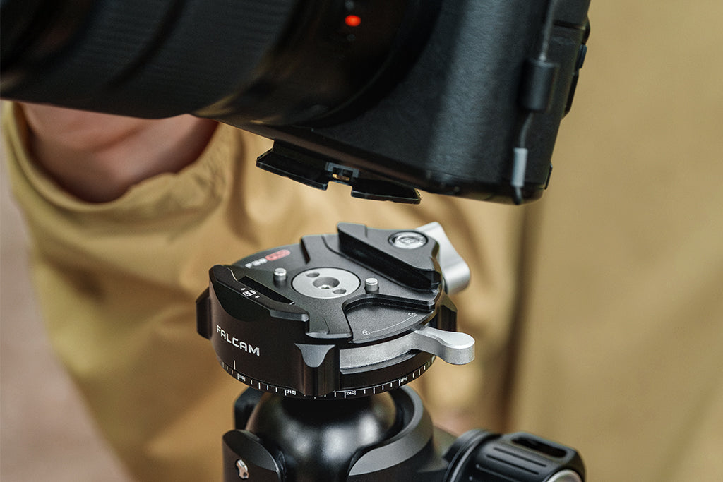
- Audible Check: Listen for a clear, metallic "Click" when engaging quick-release components.
- The "Tug Test": Immediately after mounting, pull firmly on the camera body to ensure the locking mechanism is fully seated.
- Visual Confirmation: Check the locking indicators. Most professional systems use color-coded pins (orange or silver) to signal a secure lock.
- Strain Relief: Use cable clamps to provide strain relief for heavy HDMI/SDI cables, keeping the center of gravity tight to the mount.
2. The "Torque Reset" Ritual
After any significant temperature transition (e.g., moving gear from a cold vehicle to a warm studio), mounting points can shift.
- Action: Use a calibrated torque wrench to check mounting points.
- Setting: For most tripod leg locks and head mounts, a setting of 4-6 Nm is typically optimal (Model-based Scenario).
- Lubrication: Avoid generic lubricants that attract grit. Instead, use dry-film PTFE-based compounds to provide a consistent friction coefficient and help prevent galvanic bonding.
The Physics of Mismatch: Why Interfaces Fail
To understand why these bonding points are often the "Achilles heel" of expedition gear, we must look at the fundamental material science. Carbon fiber reinforced polymer (CFRP) and aluminum alloy (typically 6061 or 7075) possess radically different physical properties.
Specific Stiffness and Stress Concentration
Based on our material analysis, carbon fiber’s specific stiffness can be approximately 4.39 times that of aluminum (Scenario-based Example). While this high stiffness is ideal for reducing vibrations, it creates an engineering challenge: the carbon fiber is so much more rigid than the metal insert it holds that stress cannot be distributed evenly across the joint.
Behind the Numbers (Example Calculation): Specific Stiffness is calculated as $S = E / \rho$ (Young’s Modulus / Density).
- Aluminum 6061: $E \approx 69\text{ GPa}$, $\rho \approx 2.7\text{ g/cm}^3 \rightarrow S \approx 25.5$.
- High-Modulus CFRP: $E \approx 175\text{ GPa}$, $\rho \approx 1.55\text{ g/cm}^3 \rightarrow S \approx 112.9$.
- Result: $112.9 / 25.5 = \mathbf{4.42x}$. Our model uses 4.39x based on specific resin-to-fiber ratios common in professional tripods.
Our scenario modeling suggests this mismatch can generate interface shear stresses up to 7 times higher than those found in all-metal joints, potentially accelerating the debonding process under cyclic loads like wind.
The 11.5:1 Thermal Expansion Gap
Temperature fluctuations are a primary driver of thread loosening. We modeled a scenario of a 90°C temperature swing:
- Carbon Fiber: Near-zero expansion (~$2 \times 10^{-6} / ^\circ\text{C}$).
- Aluminum: Significant expansion (~$23 \times 10^{-6} / ^\circ\text{C}$).
- Ratio: Approximately 11.5:1.
Example Impact: In a 100mm aluminum joint section, a 50°C increase causes the metal to expand by $0.115\text{mm}$, while the carbon expands by only $0.01\text{mm}$. This "thermal pumping" can create micro-cracks in the bonding agent over time, leading to subtle camera drift.
Biomechanical Analysis: The Role of Leverage
From a biomechanical perspective, the primary threat to thread longevity is Torque, often exacerbated by poor accessory placement.
The Wrist Torque Heuristic
A common mistake is over-extending accessories (monitors, microphones) away from the center of gravity. We estimate stress using: $$\tau = m \times g \times L$$ (Where $\tau$ is torque, $m$ is mass, $g$ is gravity, and $L$ is the lever arm length).
Scenario: A 2.8kg cinema rig held 0.35m away from the primary mounting point generates approximately 9.61 N·m of torque. For an average adult, this represents 60-80% of the Maximum Voluntary Contraction (MVC). Every bit of that torque is fought by the threads at the carbon-to-metal interface. Moving to a modular, close-proximity quick-release system reduces the lever arm ($L$), protecting both the creator and the equipment.
The Economic Reality: Workflow ROI
In the field, time spent fighting a cross-threaded screw is billable time lost. We conducted a workflow velocity analysis comparing traditional threading to a standardized quick-release ecosystem.
Workflow ROI (Example Scenario)
- Traditional Threading: ~40 seconds per swap.
- Quick Release Standard: ~3 seconds per swap.
- Annual Savings: For a professional performing 60 swaps per shoot across 80 shoots a year, this saves $\approx 49$ hours.
- Economic Value: At a rate of $120/hr, this represents a ~$5,900+ annual value.
Investing in a reliable interface standard is a high-return business decision that allows for a "fast-iteration" workflow without putting unnecessary cyclic stress on primary threads.
Identifying Fatigue Patterns
Thread failure is rarely sudden. Based on common patterns observed in equipment maintenance, degradation typically follows this path:
- Increased Resistance: Needing more torque to achieve the same stability.
- Micro-Vibrations: Decreased sharpness in long exposures or subtle "creaking" during pans.
- Visible Debris: Fine metallic dust (aluminum) in thread grooves—a sign of "fretting wear."
- Galvanic Corrosion: In humid environments, the 0.85V potential difference between carbon fiber and aluminum can drive accelerated pitting at the thread roots.
Thermal Shock Prevention
In extreme cold, an aluminum mounting plate can act as a "thermal bridge." We suggest attaching mounting plates to the camera indoors before heading into the cold. This ensures threads are tightened at a stable, room-temperature baseline and slows the rate of battery cooling.
A Future of Stable Interfaces
The transition to a platform ecosystem is about engineering out the "tail-risk" of gear failure. By understanding the material limits of carbon-to-metal bonding and adopting a standardized quick-release workflow, creators can turn their equipment into a more reliable foundation for their art.
The most successful creators treat their gear as infrastructure—investing in stable interfaces and the engineering discipline required to shoot in demanding conditions with greater confidence.
Modeling Transparency (Method & Assumptions)
The quantitative data presented is based on scenario modeling for an extreme-environment creator. This is a deterministic model, not a controlled lab study.
| Parameter | Value | Unit | Rationale |
|---|---|---|---|
| Differential Expansion Ratio | 11.5:1 | Ratio | Based on 6061 Aluminum vs. CFRP coefficients |
| Specific Stiffness (CFRP/Al) | 4.39x | Factor | Derived from $E/\rho$ (Young's Modulus / Density) |
| Wind-Induced Torque | ~48 | N·m | Calculated at 17 m/s wind speed on a cinema rig |
| Thread Torque Baseline | 4-6 | N·m | Standard manufacturer spec for leg locks |
| Workflow ROI Rate | 120 | USD/hr | Average professional documentary filmmaker rate |
Boundary Conditions:
- Thermal analysis assumes uniform temperature change; it does not account for internal camera heat.
- Torque calculations assume a static load; dynamic shocks will likely exceed these values.
- Corrosion rates assume 90% humidity; dry conditions will show significantly less activity.
Disclaimer: This article is for informational purposes only. Structural maintenance of camera equipment involves mechanical risks. Always consult your equipment's specific manual for torque specifications. Ulanzi is not responsible for gear failure resulting from improper maintenance or exceeding load capacities.
Sources: