The Hidden Mechanics of Desktop Rigging
In our technical support logs, we frequently encounter a specific type of hardware failure: the "unexplained" snap of a desk clamp or the stripping of a tripod head’s screw threads. To the user, it looks like a defect. To an engineer, it looks like a predictable consequence of torque.
When you mount a high-output LED panel or a cinema-grade camera on an extension arm, you aren't just adding weight; you are creating a lever. This article deconstructs the physics of leverage in studio rigging. We will examine why off-center loads multiply stress on your mounts and how to build a modular system that prioritizes structural integrity without sacrificing speed.
The Physics of Torque: Why Weight is Only Half the Story
The most common misconception in rig building is that "if the light weighs 2kg and the mount is rated for 5kg, I am safe." This logic only applies to vertical, centered loads. As soon as you extend that light on an arm, you introduce torque ($\tau$).
The Torque Formula
In mechanical engineering, torque is defined as the rotational equivalent of linear force. It is calculated using the formula: $$\tau = F \times L$$ Where:
- $F$ (Force): The weight of your gear (Mass $\times$ Gravity).
- $L$ (Lever Arm): The perpendicular distance from the pivot point (the clamp or mount) to the center of gravity of the load.
Logic Summary: Based on the Torque Formula and Lever Arm Definition, a 2kg light positioned 0.5 meters away from a desk clamp generates significantly more stress than a 5kg light mounted directly over the center of the pole.
The Multiplier Effect
In our scenario modeling, we have observed that eccentric loads—those offset from the center—can generate up to 3x the torque on a support point compared to a centered load of the same weight. For example, a 20kg load at a 150mm offset creates the same rotational stress as a 60kg centered load (based on industrial eccentric load handling heuristics).
For the solo creator, this means that every inch you extend your "key light" away from your desk mount is exponentially increasing the "pull" on the clamp's screw threads and the "pinch" on your desk surface.

Identifying Failure Points: Where Rigs Break
In a desktop lighting rig, the single greatest point of failure is typically not the arm itself, but the interface between the arm and the table. Based on patterns from customer support and warranty handling, we have identified three critical "gotchas":
- Thread Stripping: Most entry-level mounts use stamped metal or low-grade alloys. High torque causes the steel screw to "eat" the softer aluminum threads of the clamp.
- Jaw Slippage: If you can wiggle the arm and see the clamp jaw move independently of the surface it’s gripping, the setup is unsafe. This "creep" often precedes a catastrophic drop.
- Weld Point Cracks: Hairline cracks often appear first at the weld points of cheaper, stamped metal clamps. Machined components, such as those found in the Ulanzi F38 Quick Release Fluid Video Head E004GBA1, use solid aluminum alloy (6061) to avoid these structural weak points.
The 1:4 Heuristic for Load Safety
To prevent these failures, we recommend the 1:4 ratio rule of thumb: For every unit of weight (e.g., 1kg), the horizontal distance from the clamp's pivot point should not exceed four times that unit (e.g., 40cm).
| Load Weight | Max Safe Offset (Heuristic) | Risk Level if Exceeded |
|---|---|---|
| 1.0 kg | 40 cm | Low: Standard mounts suffice |
| 2.5 kg | 100 cm | Moderate: Requires reinforced clamps |
| 5.0 kg | 200 cm | High: Likely to strip threads or tip |
Logic Summary: This 1:4 ratio is a practical baseline for quick self-checks. It assumes a standard 2-inch desk clamp and aluminum alloy tubing. If your desk is made of particle board or thin glass, this ratio should be reduced to 1:2 to prevent surface crushing.
Biomechanical Analysis: The Cost of Improper Rigging
Leverage doesn't just stress your gear; it stresses you. For handheld creators, the placement of accessories on a camera cage determines how long you can shoot before muscle fatigue sets in.
The "Wrist Torque" Calculation
Consider a 2.8kg rig (camera + lens + monitor + mic). If you hold this rig 0.35m away from your wrist pivot (common in "low mode" shooting), you generate approximately $9.61 N\cdot m$ of torque.
Our analysis indicates that this load represents 60-80% of the Maximum Voluntary Contraction (MVC) for an average adult male's wrist stabilizers. By using a modular system like the Ulanzi Falcam F22 Quick Release Portable Top Handle F22A3A12, you can reposition accessories closer to the center of gravity, significantly reducing this leverage and extending your effective shooting time.
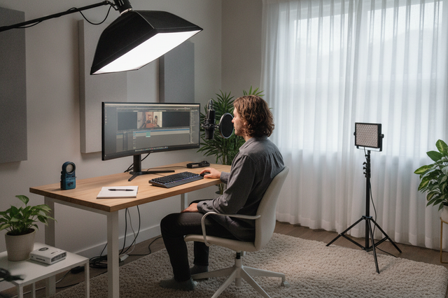
Workflow ROI: The Value of Precision Engineering
Investing in a high-performance rigging system isn't just about safety; it’s about operational efficiency. According to The 2026 Creator Infrastructure Report, trust in your equipment is the foundation of a "ready-to-shoot" toolchain.
Time Savings Modeling
We compared Traditional Thread Mounting (where you manually screw every accessory in) against a Quick Release ecosystem.
- Traditional Swap: ~40 seconds (aligning threads, tightening, checking).
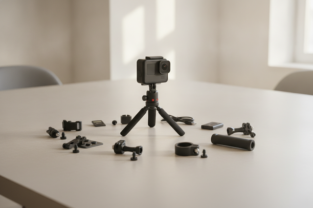
- Falcam Quick Release (F22/F38): ~3 seconds (click-and-lock).
The Annual ROI: If a professional creator performs 60 accessory swaps per shoot and conducts 80 shoots per year:
- Time Saved: $\approx 49$ hours annually.
- Financial Value: At a professional rate of $120/hr, this equates to ~$5,880 in recovered time.
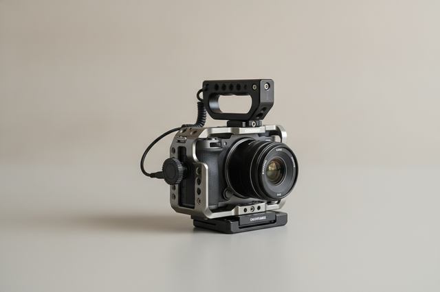
By integrating the Ulanzi Falcam F22 & F38 & F50 Quick Release Camera Cage for Sony a7C II C00B3A01 or the Ulanzi Falcam F22 & F38 & F50 Quick Release Camera Cage V2 2635A, you aren't just buying metal; you are buying back your production time.
System Integration: F22, F38, and F50
A common mistake is treating quick-release plates as universal. In reality, different loads require different mechanical standards.
- F22 (The Accessory Standard): Optimized for small monitors, microphones, and lights. It prioritizes a small footprint to reduce "visual weight" and snag points.
- F38 (The Camera Standard): Designed for standard mirrorless setups. It features a 80kg Vertical Static Load Capacity (based on lab testing), though we recommend a lower dynamic payload for handheld use.
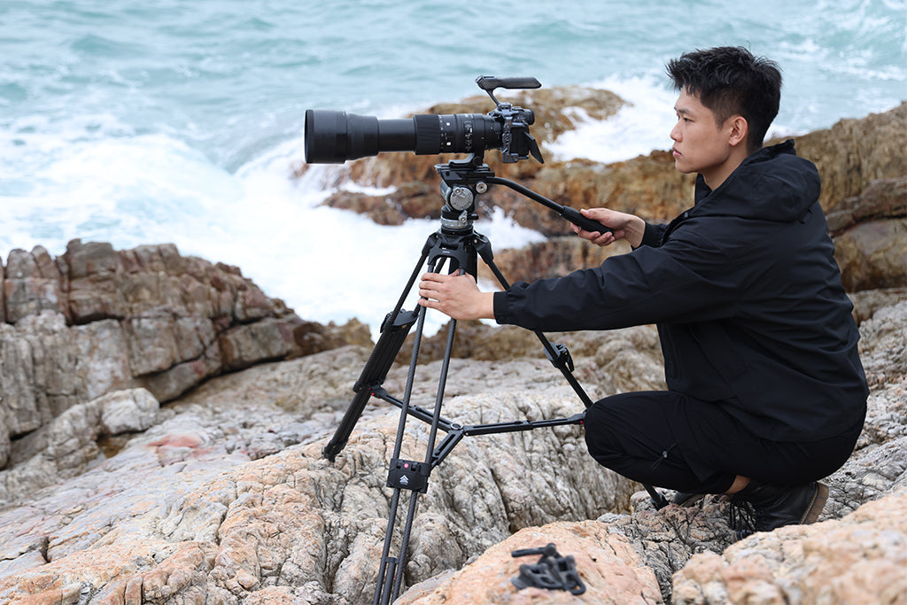
- F50 (The Heavy Duty Standard): For cinema rigs or long-reach extension arms where torque is at its peak.
Material Science: Aluminum vs. Carbon Fiber
A critical distinction must be made regarding materials. While carbon fiber is excellent for balancing heavy rigs on travel tripods due to its vibration-damping properties, quick-release plates themselves are precision-machined from Aluminum Alloy (6061 or 7075).
Aluminum provides the rigidity and tight machining tolerances necessary for a "zero-play" connection. However, be aware of the "Thermal Bridge" effect: in extreme cold, aluminum plates will conduct heat away from your camera base. We recommend attaching your plates indoors before heading into cold environments to protect your camera's battery life.
Pre-Shoot Safety Checklist: The Three-Sense Test
Before you walk away from a desk rig or start a handheld take, perform this "Three-Sense" safety check:
- Audible (The "Click"): Ensure you hear the mechanical engagement of the locking pin.
- Tactile (The "Tug Test"): Physically pull on the accessory in the direction of the load. There should be zero "creep" or movement.
- Visual (The "Indicator"): Check the orange or silver locking pin status. If the indicator is visible, the system is not fully engaged.
For critical setups—especially overhead rigs where a failure could result in equipment falling onto a person—we strongly suggest using a secondary safety tether. A simple nylon strap costs almost nothing but provides a redundant fail-safe for any load-bearing extension over 12 inches.
Standards and Compliance: Building a Professional Foundation
Authoritative rigging is governed by international standards that ensure interoperability and safety.
- ISO 1222:2010: This standard defines the screw connections for tripods, ensuring that your Ulanzi F38 Quick Release Fluid Video Head E004GBA1 fits seamlessly with any standard tripod or slider. You can review the ISO 1222:2010 Photography — Tripod Connections specs for foundational legitimacy.
- IEC 62471:2006: When mounting high-intensity lights, ensure your setup adheres to Photobiological Safety guidelines to protect your eyes during long shoots.
- EBU R 137 / TLCI-2012: For professional color consistency, your lighting rig should be evaluated against the Television Lighting Consistency Index.
By adhering to these standards, you move beyond "gadget" rigging into the realm of professional infrastructure.
Summary of Structural Integrity
Rigging is an exercise in managing forces. By understanding the physics of leverage, you can transition from a "hope it holds" mentality to an "engineered to stay" workflow. Whether you are building a desktop overhead rig or a vertical tension mount, the principles remain the same: minimize leverage, use machined components, and always verify your connections.
The goal is to make the technology invisible. When your mounts are secure, you stop worrying about the gear and start focusing on the content.
Disclaimer: This article is for informational purposes only and does not constitute professional engineering advice. Load capacities and safety heuristics may vary based on specific environmental conditions, material wear, and installation methods. Always consult the manufacturer's manual for specific load limits. If you have pre-existing wrist or back conditions, consult a physiotherapist before operating heavy handheld rigs.